Nissan Versa (N17): High-mounted stop lamp
Exploded View
Rear Spoiler
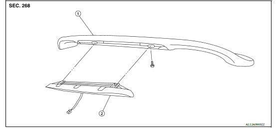
1. Rear spoiler 2. High-mounted stop lamp assembly
Rear Parcel Shelf
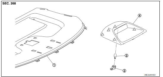
1. Rear parcel shelf finisher 2. High-mounted stop lamp socket 3.
High-mounted stop lamp bulb
4. High-mounted stop lamp housing  Pawl
Pawl
Removal and Installation
HIGH-MOUNTED STOP LAMP - REAR SPOILER
Removal
1. Remove the rear spoiler. Refer to EXT "Removal and Installation".
2. Remove screws and the high-mounted stop lamp.
Installation
Installation is in the reverse order of removal.
HIGH-MOUNTED STOP LAMP - PARCEL SHELF
Removal
1. Fully open trunk lid assembly.
2. Rotate the bulb socket counterclockwise.
3. Release high-mounted stop lamp pawls and remove high-mounted stop lamp housing.
Installation
Installation is in the reverse order of removal.
Bulb Replacement
WARNING: Do not touch bulb with your hand while it is on or right after being turned off. Burning may result.
CAUTION:
- Do not touch the glass surface of the bulb with bare hands or allow oil or grease to get on it to prevent damage to the bulb.
- Do not leave bulb out of lamp reflector for a long time because dust, moisture smoke, etc. may affect the performance of lamp. When replacing bulb, be sure to replace it with new one.
HIGH-MOUNTED STOP LAMP BULB - REAR SPOILER
The high-mounted stop lamp bulb is a LED and is integrated into the high-mounted stop lamp and is serviced as an assembly. Refer to EXL "Removal and Installation".
HIGH-MOUNTED STOP LAMP BULB - PARCEL SHELF
Removal
1. Fully open trunk lid assembly.
2. Rotate the bulb socket counterclockwise and remove.
3. Remove the bulb from the bulb socket.
Installation
Installation is in the reverse order of removal.
 Rear combination lamp
Exploded View 1. Rear combination lamp 2. Grommet Clip ...
License plate lamp
Exploded View 1. License plate lamp 2. License plate lamp bulb ...
Other materials:
Control linkage
Exploded View
1. Shifter lever A 2. Selector lever 3. Selector cable
4. Shifter cable 5. Cable mounting bracket 6. Tapping bolt
7. Bracket 8. Grommet 9. M/T shift selector assembly
10. Shift selector 11. Shift selector handle
Removal and Installation
REMOVAL
Move the shift selector to ...
Low tire pressure warning lamp
does not turn off
Diagnosis Procedure
1.INSPECT BCM CONNECTOR
Turn ignition switch OFF.
Disconnect BCM connectors.
Check terminals for damage or loose connections.
Is the inspection result normal?
YES >> GO TO 2.
NO >> Repair or replace damaged parts.
2.BCM POWER SUPPLY AND GROUND CIRCUITS ...
Categories
- Manuals Home
- Nissan Versa Owners Manual
- Nissan Versa Service Manual
- Video Guides
- Questions & Answers
- External Resources
- Latest Updates
- Most Popular
- Sitemap
- Search the site
- Privacy Policy
- Contact Us

0.0061