Nissan Versa (N17): Transaxle assembly
Exploded View
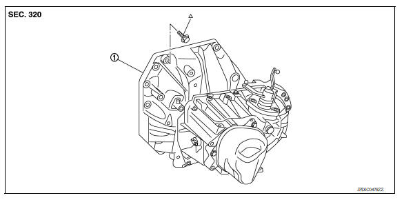
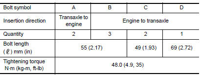
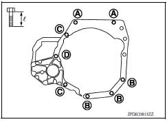
1. Transaxle assembly
 : Refer to "INSTALLATION" in TM,
"Removal and Installation" for the locations and tightening torque.
: Refer to "INSTALLATION" in TM,
"Removal and Installation" for the locations and tightening torque.
Removal and Installation
CAUTION: Do not reuse CSC (concentric slave cylinder). CSC slides back to the original position every time transaxle assembly is removed. Dust on the sliding parts may damage the seal of CSC and may cause clutch fluid leakage. Refer to CL, "Removal and Installation".
NOTE: When removing components such as hoses, tubes/lines, etc., cap or plug openings to prevent fluid from spilling.
REMOVAL
- Move the shift selector to the neutral position.
- Remove battery. Refer to PG, "Removal and Installation".
- Remove air cleaner case. Refer to EM, "Removal and Installation".
- Remove IPDM E/R bracket bolts (A) and nut (B).
 : Front
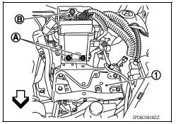
- Remove IPDM E/R bracket (1).
- Remove air breather hose. Refer to TM, "Removal and Installation".
- Disconnect selector cable and shifter cable from transaxle assembly. Refer to TM, "Removal and Installation".
- Remove drive shaft heat insulator.
- Remove crankshaft position sensor. Refer to EM, "Exploded View".
- Remove clutch tube clip from engine mounting bracket (LH).
- Remove clutch tube from CSC and then temporarily position it aside. Refer to CL, "Removal and Installation".
CAUTION:
- Keep painted surface on the body or other parts free of clutch fluid. If it spills, wipe up immediately and wash the affected area with water.
- Do not depress clutch pedal during removal procedure.
- Remove fender protector (LH). Refer to EXT, "Removal and Installation".
- Disconnect ground cable.
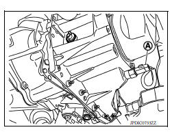
- Disconnect harness connector (A) from position switch.
- Remove the harness clamp from rear housing.
- Remove the engine harness clamp and then position it aside.
- Remove starter motor. Refer to STR, "Removal and Installation".
- Remove front drive shafts. Refer to FAX, "Removal and Installation".
- Set a suitable jack to transaxle assembly and then set a suitable jack to engine assembly.
CAUTION: When setting a suitable jack, be careful that it does not contact the position switch.
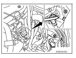
20. Remove engine mounting frame support (LH) bolts.
a. Remove bolt (A).
: Front
b. Release clutch damper (1) from bracket. Refer to CL, "Removal and Installation".
c. Remove bolt (B).
d. Remove engine mounting bracket (LH) bolts from vehicle. Refer to EM, "Exploded View".
21. Remove rear engine mounting bracket and rear torque rod.
Refer to EM, "Exploded View".
22. Remove transaxle assembly bolts and nuts.
23. Remove transaxle assembly from the engine.
CAUTION:
- Secure transaxle assembly to a suitable jack.
- The transaxle assembly must not interfere with the wire harnesses and clutch tube.
24. Remove engine mounting bracket (LH) from transaxle assembly. Refer to EM, "Exploded View".
25. Remove CSC. Refer to CL, "Removal and Installation".
INSTALLATION
Installation is in the reverse order of removal.
CAUTION:
- Secure transaxle assembly to a suitable jack.
- The transaxle assembly must not interfere with the wire harnesses and clutch tube.
- When installing transaxle assembly, do not bring input shaft into contact with clutch cover.
- Bolt hole is not threaded on new clutch housing. Self-tapping bolt is used to attach lock plate to clutch housing.
- Do not reuse self-tapping bolt.
- Tighten transaxle assembly bolts to the specified torque. The
illustration
is the view from the engine.
Inspection
INSPECTION AFTER INSTALLATION
- Check the operation of the control linkage. Refer to TM, "Inspection".
- Before starting engine, check oil/fluid levels including engine coolant and engine oil. If less than required quantity, fill to the specified level. Refer to MA, "Fluids and Lubricants".
- Use procedure below to check for fuel leakage.
- Turn ignition switch ON (with engine stopped). With fuel pressure applied to fuel piping, check for fuel leakage at connection points.
- Start engine. With engine speed increased, check again for fuel leakage at connection points.
- Run engine to check for unusual noise and vibration.
NOTE:If hydraulic pressure inside timing chain tensioner drops after removal and installation, slack in the guidemay generate a pounding noise during and just after engine start. However, this is normal. Noise will stopafter hydraulic pressure rises.
- Warm up engine thoroughly to make sure there is no leakage of fuel, exhaust gas, or any oils/fluids includingengine oil and engine coolant.
- Bleed air from passages in lines and hoses, such as in cooling system.
- After cooling down engine, again check oil/fluid levels including engine oil and engine coolant. Refill to specifiedlevel, if necessary.
- Summary of the inspection items:
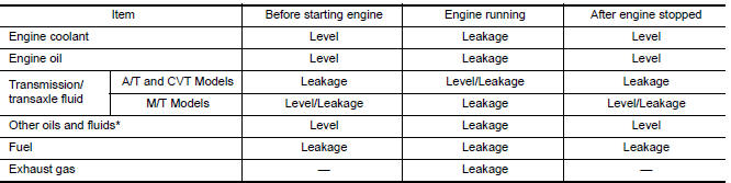
*Power steering fluid, brake fluid, etc.
 5Th main gear assembly
Removal and Installation REMOVAL Move the shift selector to the 3rd gear position. Disconnect the shifter cable and the selector cable from shifter lever A and selector lever. Refer to TM, ...

Other materials:
Specifications
Engine
This spark ignition system complies with the Canadian standard ICES-002.
Wheels and tires
Dimensions and weights
...
P0712 Transmission fluid temperature
sensor A
DTC Logic
DTC DETECTION LOGIC
DTC
Trouble diagnosis name
DTC detection condition
Possible causes
P0712
Transmission Fluid Temperature
Sensor A Circuit Low
The CVT fluid temperature identified by the
TCM is 180C (356F) or more continuously
for 5 seconds or ...
Categories
- Manuals Home
- Nissan Versa Owners Manual
- Nissan Versa Service Manual
- Video Guides
- Questions & Answers
- External Resources
- Latest Updates
- Most Popular
- Sitemap
- Search the site
- Privacy Policy
- Contact Us

0.0056