Nissan Versa (N17): Steering switch
Diagnosis Procedure
Regarding Wiring Diagram information, refer to AV "Wiring Diagram".
1.CHECK STEERING WHEEL AUDIO CONTROL SWITCH RESISTANCE
1. Turn ignition switch OFF.
2. Disconnect combination switch connector M88.
3. Check resistance between the terminals of combination switch connector
M88.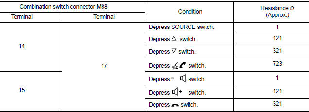
Is the inspection result normal?
YES >> GO TO 2.
NO >> Replace steering switches. Refer to AV "Removal and Installation".
2.CHECK HARNESS BETWEEN BLUETOOTH CONTROL UNIT AND COMBINATION SWITCH
1. Disconnect Bluetooth control unit connector B33 and combination switch connector M30.
2. Check continuity between Bluetooth control unit connector B33 and
combination switch connector M30.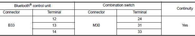
3. Check continuity between Bluetooth control unit connector B33 and ground.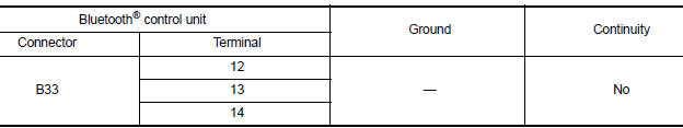
Is the inspection result normal?
YES >> GO TO 3.
NO >> Repair or replace harness or connectors.
3.CHECK COMBINATION SWITCH
Check continuity between combination switch connectors M88 and M30.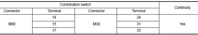
Is the inspection result normal?
YES >> GO TO 4.
NO >> Replace spiral cable. Refer to SR "Removal and Installation".
4.CHECK HARNESS BETWEEN BLUETOOTH CONTROL UNIT AND AUDIO UNIT
1. Disconnect audio unit connector M44.
2. Check continuity between Bluetooth control unit connector B33 and audio
unit connector M44.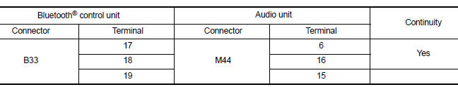
3. Check continuity between Bluetooth control unit connector B33 and ground.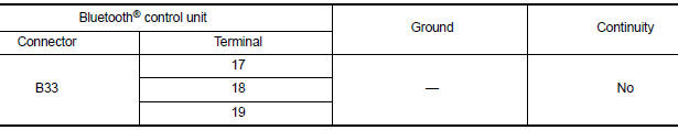
Is the inspection result normal?
YES >> Replace audio unit. Refer to AV "Removal and Installation".
NO >> Repair or replace harness or connectors.
SYMPTOM DIAGNOSIS
 Microphone signal circuit
Diagnosis Procedure Regarding Wiring Diagram information, refer to AV"Wiring Diagram". 1.CHECK HARNESS BETWEEN BLUETOOTH CONTROL UNIT AND MICROPHONE 1. Turn ignition switch OFF. 2. Disco ...
Audio system
Symptom Table RELATED TO AUDIO RELATED TO HANDS-FREE PHONE Before performing diagnosis, confirm that the cellular phone being used by the customer is compatible with the vehicl ...
Other materials:
Exhaust system
Exploded View
1. Heated oxygen sensor 2 2. Catalyst cover (upper) 3. Seal bearing
4. Catalyst cover (lower) 5. Spring 6. Spring
7. Mounting rubber 8. Main muffler 9. Ring gasket
10. Center muffler 11. Mounting rubber 12. Seal bearing
13. Exhaust front tube
Removal and Installation
WARNIN ...
P0740 Torque converter
DTC Logic
DTC DETECTION LOGIC
DTC
Trouble diagnosis name
DTC detection condition
Possible causes
P0740
Torque Converter Clutch Circuit/
Open
The follow diagnosis conditions
are met, and the TCM torque
converter clutch solenoid valve
current monitor readin ...
Categories
- Manuals Home
- Nissan Versa Owners Manual
- Nissan Versa Service Manual
- Video Guides
- Questions & Answers
- External Resources
- Latest Updates
- Most Popular
- Sitemap
- Search the site
- Privacy Policy
- Contact Us

0.0051