Nissan Versa (N17): Microphone signal circuit
Diagnosis Procedure
Regarding Wiring Diagram information, refer to AV"Wiring Diagram".
1.CHECK HARNESS BETWEEN BLUETOOTH CONTROL UNIT AND MICROPHONE
1. Turn ignition switch OFF.
2. Disconnect Bluetooth control unit connector B33 and microphone connector R15.
3. Check continuity between Bluetooth control unit connector B33 and
microphone connector R15.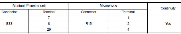
4. Check continuity between Bluetooth control unit connector B33 and ground.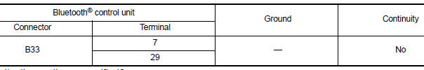
Are continuity results as specified?
YES >> GO TO 2
NO >> Repair harness or connectors.
2.CHECK MICROPHONE POWER SUPPLY
1. Connect Bluetooth control unit connector B33 and microphone connector R15.
2. Turn ignition switch ON.
3. Check voltage between microphone connector R15 and ground.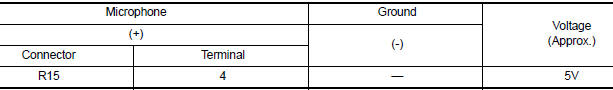
Is the voltage reading as specified?
YES >> GO TO 3
NO >> Replace Bluetooth control unit. Refer to AV "Removal and Installation".
3.CHECK MICROPHONE SIGNAL
Check signal between terminals of Bluetooth control unit connector B33.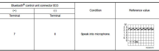
Were voltage readings as specified?
YES >> Replace Bluetooth control unit. Refer to AV "Removal and Installation".
NO >> Replace microphone. Refer to AV "Removal and Installation".
 Bluetooth control signal circuit
Diagnosis Procedure Regarding Wiring Diagram information, refer to AV "Wiring Diagram". 1.CHECK CONTROL SIGNAL CIRCUIT CONTINUITY 1. Turn ignition switch OFF. 2. Disconnect Bluetooth con ...
Steering switch
Diagnosis Procedure Regarding Wiring Diagram information, refer to AV "Wiring Diagram". 1.CHECK STEERING WHEEL AUDIO CONTROL SWITCH RESISTANCE 1. Turn ignition switch OFF. 2. Disconnect ...
Other materials:
P0973 Shift solenoid A
DTC Logic
DTC DETECTION LOGIC
DTC
Trouble diagnosis name
DTC detection condition
Possible causes
P0973
Shift Solenoid "A" Control Circuit
Low
The following diagnosis conditions
are met, and the TCM select
switch ON-OFF solenoid
valve monitor value is ON c ...
Shift position indicator circuit
Component Parts Function Inspection
1.CHECK SHIFT POSITION INDICATOR
Start the engine.
Shift selector lever.
Check that the selector lever position and the shift position indicator
on the combination meter are identical.
Is the inspection result normal?
YES >> INSPECTION END
N ...
Categories
- Manuals Home
- Nissan Versa Owners Manual
- Nissan Versa Service Manual
- Video Guides
- Questions & Answers
- External Resources
- Latest Updates
- Most Popular
- Sitemap
- Search the site
- Privacy Policy
- Contact Us

0.0074