Nissan Versa (N17): System
System Diagram
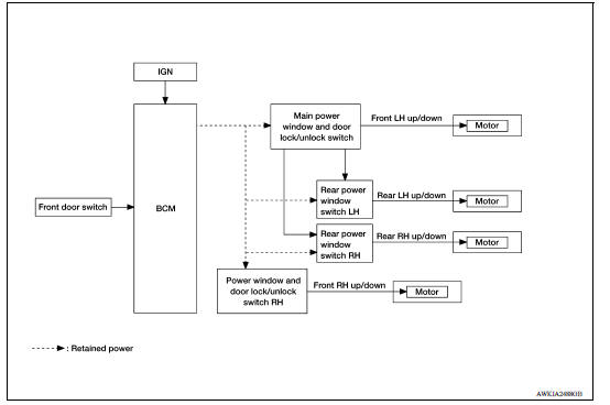
System Description
BASIC OPERATION
- Power window system is activated by power window switch when ignition switch turns ON.
- Power window main switch opens/closes all door glass.
- Front and rear power window switch opens/closes the corresponding door glass.
- AUTO DOWN operation can be performed when power window main switch is depressed to the second detent.
- Power window lock switch can lock all power windows other than driver seat.
POWER WINDOW AUTO-OPERATION (FRONT DRIVER SIDE)
AUTO DOWN operation can be performed when power window main switch is depressed to the second detent.
POWER WINDOW LOCK
Ground circuit inside power window main switch shuts off when power window lock switch is ON. This inhibits each power window switch operation except the power window main switch.
RETAINED POWER OPERATION
- Retained power operation is an additional power supply function that
enables power window system to operate
for an additional 45 seconds after the ignition switch is turned OFF.
RETAINED ACCESSORY POWER CANCEL CONDITIONS:
- Front door CLOSE (door switch OFF)→OPEN (door switch ON).
- When ignition switch is ON again.
- When timer expires. (45 seconds)
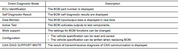
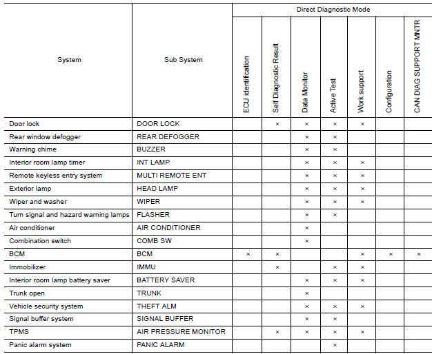
DIAGNOSIS SYSTEM (BCM) (WITH INTELLIGENT KEY SYSTEM)
COMMON ITEM
COMMON ITEM : CONSULT Function (BCM - COMMON ITEM)
APPLICATION ITEM
CONSULT performs the following functions via CAN communication with BCM.
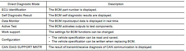
SYSTEM APPLICATION
BCM can perform the following functions.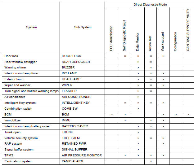
RETAINED PWR
RETAINED PWR : CONSULT Function (BCM - RETAINED PWR)
DATA MONITOR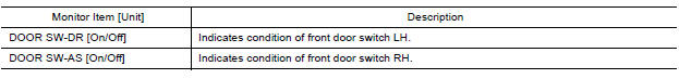
DIAGNOSIS SYSTEM (BCM) (WITHOUT INTELLIGENT KEY SYSTEM)
COMMON ITEM
COMMON ITEM : CONSULT Function (BCM - COMMON ITEM)
APPLICATION ITEM
CONSULT performs the following functions via CAN communication with BCM.
SYSTEM APPLICATION
BCM can perform the following functions.
ECU DIAGNOSIS INFORMATION
BCM
List of ECU Reference
| ECU | Reference |
| BCM (with Intelligent Key system) | BCS "Reference Value" |
| BCS "Fail-safe" | |
| BCS "DTC Inspection Priority Chart" | |
| BCS "DTC Index" | |
| BCM (without Intelligent Key system) | BCS "Reference Value" |
| BCS "Fail-safe" | |
| BCS "DTC Inspection Priority Chart" | |
| BCS "DTC Index" |
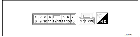
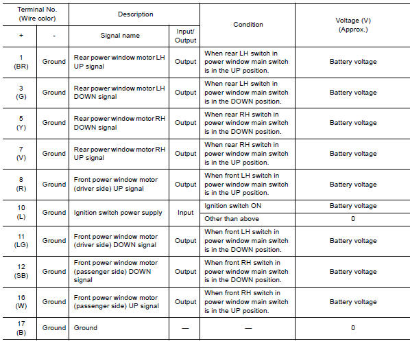
POWER WINDOW MAIN SWITCH
Reference Value
TERMINAL LAYOUT
PHYSICAL VALUES
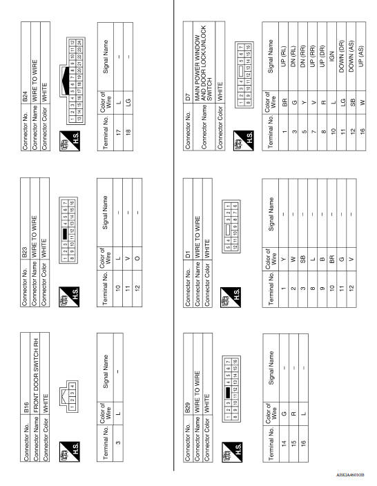
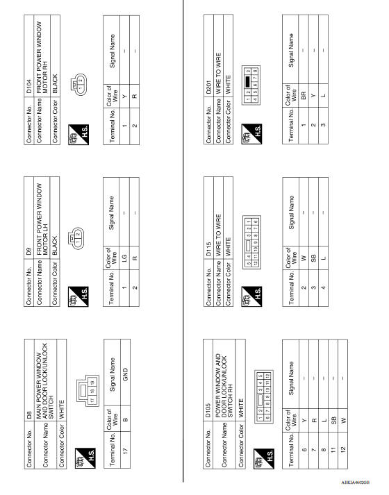
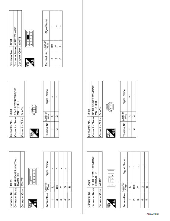
WIRING DIAGRAM
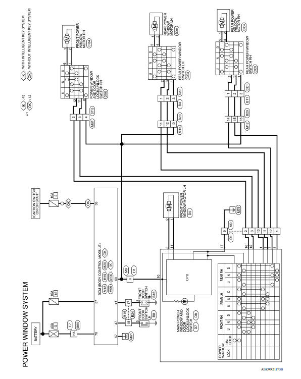
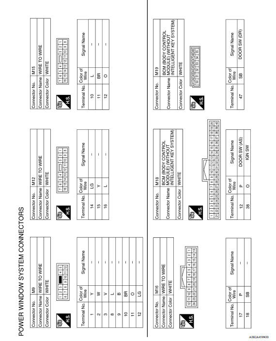
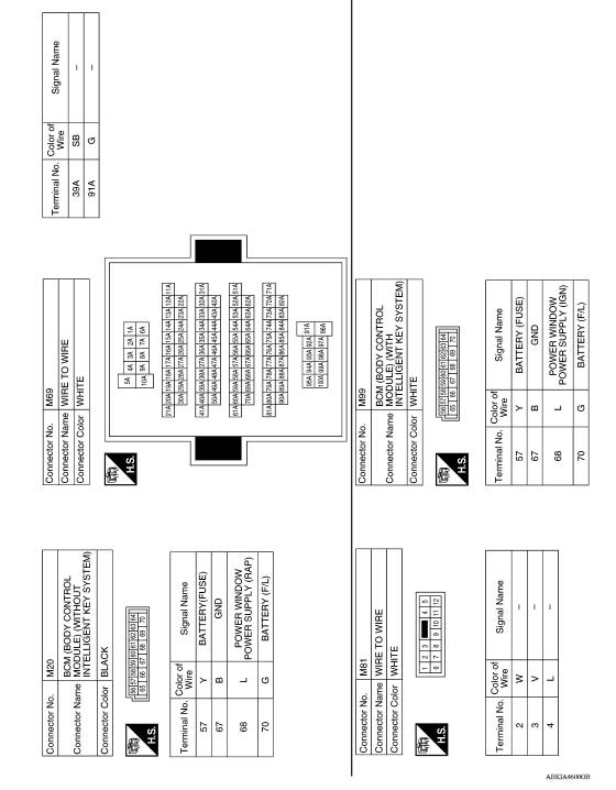
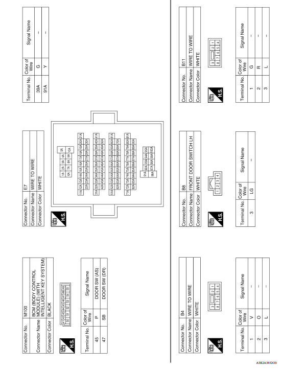
POWER WINDOW SYSTEM
Wiring Diagram
BASIC INSPECTION
 Precautions
Diagnosis and repair work flow
Work Flow OVERALL SEQUENCE DETAILED FLOW 1. OBTAIN INFORMATION ABOUT SYMPTOM Interview the customer to obtain as much information as possible about the conditions and environment under whi ...
Other materials:
Cleaning interior
Occasionally remove loose dust from the interior
trim, plastic parts and seats using a vacuum
cleaner or soft bristled brush. Wipe the vinyl and
leather surfaces with a clean, soft cloth dampened
in mild soap solution, then wipe clean with a
dry, soft cloth.
Regular care and cleaning is requ ...
General maintenance
During the normal day-to-day operation of the
vehicle, general maintenance should be performed
regularly as prescribed in this section. If
you detect any unusual sounds, vibrations or
smells, be sure to check for the cause or have a
NISSAN dealer do it promptly. In addition, it is
recommended ...
Categories
- Manuals Home
- Nissan Versa Owners Manual
- Nissan Versa Service Manual
- Video Guides
- Questions & Answers
- External Resources
- Latest Updates
- Most Popular
- Sitemap
- Search the site
- Privacy Policy
- Contact Us

0.006