Nissan Versa (N17): Trunk room lamp circuit
Description
Controls the trunk room lamp (ground side) to turn the trunk room lamp ON and OFF.
Component Function Check
CAUTION: Before performing the diagnosis, check that the following is normal.
- Battery saver output/power supply
- Trunk room lamp bulb
Diagnosis Procedure
Regarding Wiring Diagram information, refer to INL "Wiring Diagram".
1.CHECK TRUNK ROOM LAMP OUTPUT
1. Turn ignition switch OFF.
2. Remove the trunk room bulb.
3. Check continuity between BCM harness connector and ground.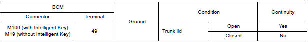
Is the inspection result normal?
YES >> GO TO 2.
Fixed ON>>GO TO 3.
Fixed OFF>>Replace BCM after making sure battery saver output/power supply circuit is not shorted to voltage.
Refer to BCS "Removal and Installation" (with Intelligent Key) or BCS "Removal and Installation" (without Intelligent Key).
2.CHECK TRUNK ROOM LAMP OPEN CIRCUIT
Check continuity between BCM harness connector and trunk room lamp harness
connector.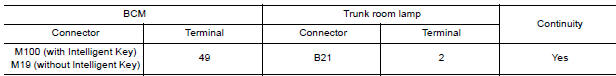
Is the inspection result normal?
YES >> Replace trunk room lamp.
NO >> Repair or replace the harness or connector.
3.CHECK TRUNK ROOM LAMP SHORT CIRCUIT
1. Disconnect BCM harness connector.
2. Check continuity between BCM harness connector and ground.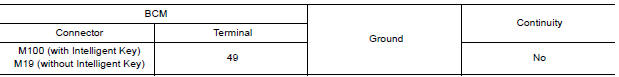
Is the inspection result normal?
YES >> Replace BCM after making sure battery saver output/power supply circuit is not shorted to voltage.
Refer to BCS "Removal and Installation" (with Intelligent Key) or BCS "Removal and Installation" (without Intelligent Key).
NO >> Repair or replace the harness or connector.
 Interior room lamp control circuit
Description Controls each interior room lamp (ground side) by PWM signal. NOTE: PWM signal control period is approximately 250 Hz (in the gradual brightening/dimming). ...
Push-button ignition switch illumination
circuit
Description Provides the power supply and the ground to control the push-button ignition switch illumination. ...
Other materials:
Power steering
WARNING
If the engine is not running or is turned
off while driving, the power assist for
the steering will not work. Steering will
be harder to operate.
When the power steering warning light
illuminates with the engine running,
there will be no power assist for the
steering. You w ...
Multiport fuel injection system
MULTIPORT FUEL INJECTION SYSTEM : System Diagram
MULTIPORT FUEL INJECTION SYSTEM : System
Description
INPUT/OUTPUT SIGNAL CHART
Sensor
Input signal to ECM
ECM function
Actuator
Crankshaft position sensor (POS)
Engine speed*4
Piston position
Fuel injection & ...
Categories
- Manuals Home
- Nissan Versa Owners Manual
- Nissan Versa Service Manual
- Video Guides
- Questions & Answers
- External Resources
- Latest Updates
- Most Popular
- Sitemap
- Search the site
- Privacy Policy
- Contact Us

0.0049