Nissan Versa (N17): U1000 CAN COMM
DTC Logic
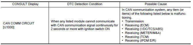
DTC DETECTION LOGIC
NOTE: U1000 can be set if a module harness was disconnected and
reconnected, perhaps during a repair. Confirm that there are actual CAN
diagnostic symptoms and a present DTC by performing the Self Diagnostic Result
procedure.
Diagnosis Procedure
1. PERFORM SELF DIAGNOSTIC RESULT
- Turn ignition switch ON and wait for 2 second or more.
- Check "SELF- DIAG RESULTS".
Is "CAN COMM CIRCUIT" displayed?
YES >> Perform CAN Diagnosis as described in DIAGNOSIS section of CONSULT Operation manual.
NO >> Refer to GI "Intermittent Incident".
U1010 CONTROL UNIT (CAN)
DTC Logic
DTC DETECTION LOGIC 
Diagnosis Procedure
1.REPLACE BCM
When DTC "U1010" is detected, replace BCM.
>> Replace BCM. Refer to BCS "Removal and Installation".
 Diagnosis and repair workflow
Work Flow OVERALL SEQUENCE DETAILED FLOW 1.GET INFORMATION FOR SYMPTOM Get the detailed information from the customer about the symptom (the condition and the environment when the incident/ ...
Power supply and ground circuit
Diagnosis Procedure Regarding Wiring Diagram information, refer to BCS "Wiring Diagram". 1.CHECK FUSES AND FUSIBLE LINK Check that the following fuses and fusible link are not blown. ...
Other materials:
Power steering
WARNING
If the engine is not running or is turned
off while driving, the power assist for
the steering will not work. Steering will
be harder to operate.
When the power steering warning light
illuminates with the engine running,
there will be no power assist for the
steering. You w ...
Air pressure monitor
AIR PRESSURE MONITOR : CONSULT Function
(BCM - AIR PRESSURE MONITOR)
NOTE:
The Signal Tech II Tool (J-50190) can be used to perform the following
functions. Refer to the Signal Tech II
User Guide for additional information.
Activate and display TPMS transmitter IDs
Display tire pressure ...
Categories
- Manuals Home
- Nissan Versa Owners Manual
- Nissan Versa Service Manual
- Video Guides
- Questions & Answers
- External Resources
- Latest Updates
- Most Popular
- Sitemap
- Search the site
- Privacy Policy
- Contact Us

0.0048