Nissan Versa (N17): U1000 CAN Comm circuit
DTC Logic
DTC DETECTION LOGIC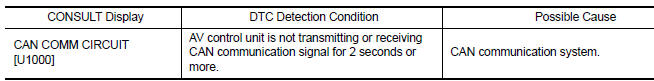
Diagnosis Procedure
1.PERFORM SELF DIAGNOSTIC RESULT
1. Turn ignition switch ON and wait for 2 seconds or more.
2. Perform Self Diagnostic Result for MULTI AV.
Is CAN COMM CIRCUIT displayed?
YES >> Refer to LAN "Trouble Diagnosis Flow Chart".
NO >> Refer to GI "Intermittent Incident".
U1010 CONTROL UNIT (CAN)
DTC Logic
DTC DETECTION LOGIC
| CONSULT Display | DTC Detection Condition | Possible Cause |
| CONTROL UNIT (CAN) [U1010] | Error during CAN controller hardware initialization (VCAN). | Replace the AV control unit if the malfunction occurs
constantly.
Refer to AV "Removal and Installation". |
U1217 AV CONTROL UNIT
DTC Logic
DTC DETECTION LOGIC
| CONSULT Display | DTC Detection Condition | Possible Cause |
| BLUETOOTH MODULE [U1217] | Connection failure to the internal Blueooth sub unit is detected. | Replace AV control unit if malfunction occurs
constantly.
Refer to AV "Removal and Installation". |
U1229 AV CONTROL UNIT
DTC Logic
DTC DETECTION LOGIC
| CONSULT Display | DTC Detection Condition | Possible Cause |
| iPod CERTIFICATION [U1229] | iPod authentication chip error. | Replace AV control unit if malfunction occurs
constantly.
Refer to AV "Removal and Installation". |
U122F AV CONTROL UNIT
DTC Logic
DTC DETECTION LOGIC
| CONSULT Display | DTC Detection Condition | Possible Cause |
| Digital broadcasting connection error [U122F] | Communication error with digital audio broadcast module internal to AV control unit. | Replace AV control unit if malfunction occurs
constantly.
Refer to AV "Removal and Installation". |
 Inspection and adjustment
U1244 GPS Antenna
DTC Logic DTC DETECTION LOGIC Diagnosis Procedure Regarding Wiring Diagram information, refer to AV "Wiring Diagram". 1.GPS ANTENNA INSPECTION Visually inspect the ...
Other materials:
NISSAN Intelligent Key (if so equipped)
WARNING
Radio waves could adversely affect
electric medical equipment. Those who
use a pacemaker should contact the
electric medical equipment manufacturer
for the possible influences before
use.
The Intelligent Key transmits radio
waves when the buttons are pressed.
The FAA ad ...
U1000 Can COMM circuit
Description
CAN (Controller Area Network) is a serial communication line for real-time
application. It is an on-vehicle multiplex
communication line with high data communication speed and excellent malfunction
detection ability.
Many electronic control units are equipped onto a vehicle, an ...
Categories
- Manuals Home
- Nissan Versa Owners Manual
- Nissan Versa Service Manual
- Video Guides
- Questions & Answers
- External Resources
- Latest Updates
- Most Popular
- Sitemap
- Search the site
- Privacy Policy
- Contact Us

0.0082