Nissan Versa (N17): U1244 GPS Antenna
DTC Logic
DTC DETECTION LOGIC
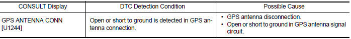
Diagnosis Procedure
Regarding Wiring Diagram information, refer to AV "Wiring Diagram".
1.GPS ANTENNA INSPECTION
Visually inspect the GPS antenna and antenna feeder. Refer to AV "Removal and Installation".
Is inspection result normal?
YES >> GO TO 2.
NO >> Repair or replace malfunctioning components.
2.CHECK AV CONTROL UNIT VOLTAGE
1. Disconnect AV control unit connector M91.
2. Turn ignition switch ON.
3. Check voltage between AV control unit connector M91 and ground.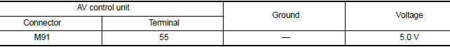
Is inspection result normal?
YES >> Replace GPS antenna. Refer to AV "Removal and Installation".
NO >> Replace AV control unit. Refer to AV "Removal and Installation".
 U1000 CAN Comm circuit
DTC Logic DTC DETECTION LOGIC Diagnosis Procedure 1.PERFORM SELF DIAGNOSTIC RESULT 1. Turn ignition switch ON and wait for 2 seconds or more. 2. Perform Self Diagnostic Result for MULTI AV. Is C ...
U1258 Satellite radio antenna
DTC Logic DTC DETECTION LOGIC Diagnosis Procedure Regarding Wiring Diagram information, refer to AV "Wiring Diagram". 1.SATELLITE ANTENNA INSPECTION Visually inspect ...
Other materials:
Doors
When the doors are locked using one of the
following methods, the doors cannot be opened
using the inside or outside door handles. The
doors must be unlocked to open the doors.
WARNING
Before opening any door, always look
for and avoid oncoming traffic.
To help avoid risk of injury or de ...
Cleaning exterior
In order to maintain the appearance of your vehicle,
it is important to take proper care of it.
To protect the paint surfaces, please wash your
vehicle as soon as you can:
After a rainfall to prevent possible damage
from acid rain.
After driving on coastal roads.
When contaminants suc ...
Categories
- Manuals Home
- Nissan Versa Owners Manual
- Nissan Versa Service Manual
- Video Guides
- Questions & Answers
- External Resources
- Latest Updates
- Most Popular
- Sitemap
- Search the site
- Privacy Policy
- Contact Us

0.0051