Nissan Versa (N17): Blower fan resistor
Exploded View
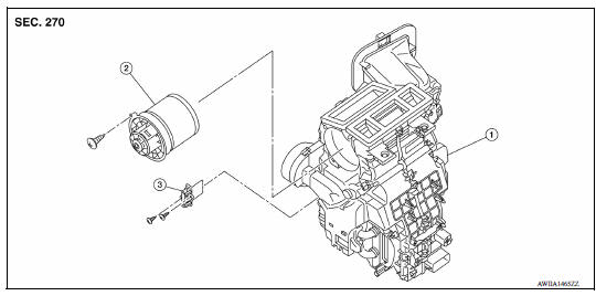
1. A/C unit assembly 2. Blower motor 3. Blower fan resistor
Removal and Installation
REMOVAL
- Remove instrument panel assembly. Refer to IP "Removal and Installation".
- Disconnect harness connector from the blower fan resistor.
- Remove screws and blower fan resistor.
INSTALLATION
Installation is in the reverse order of removal.
DOOR CABLE
Exploded View
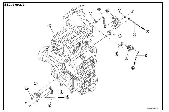
1. A/C unit assembly 2. Plate 3. Air mix door link 2 4. Air mix door link 1 5. Air mix door cable 6. Intake door lever 7. Intake door link 8. Intake door cable 9. Foot door lever 10. Mode door cable 11. Main link 12. Ventilator door rod 13. Ventilator door lever A. To A/C control
 Refrigerant pressure sensor
Removal and Installation for Refrigerant Pressure Sensor REMOVAL CAUTION: Do not damage the condenser fins. Perform lubricant return operation before each refrigeration system disassembly. ...
Intake door cable
INTAKE DOOR CABLE : Removal and Installation REMOVAL Remove instrument panel assembly. Refer to IP "Removal and Installation". Disconnect intake door cable from A/C control. Disc ...
Other materials:
Fluid cooler & fluid warmer system
FLUID COOLER & FLUID WARMER SYSTEM :
System Description
CVT FLUID COOLER SCHEMATIC
COMPONENT DESCRIPTION
CVT Oil Warmer
The CVT oil warmer (1) is installed on the front part of transaxle
assembly.
When engine is started while engine and CVT are cold, engine
coolant temperatur ...
P0965 Pressure control solenoid B
DTC Logic
DTC DETECTION LOGIC
DTC
Trouble diagnosis name
DTC detection condition
Possible causes
P0965
Pressure control solenoid B
control circuit range performance
The detection conditions continuously for 5
seconds or more under the following diagnosis
con ...
Categories
- Manuals Home
- Nissan Versa Owners Manual
- Nissan Versa Service Manual
- Video Guides
- Questions & Answers
- External Resources
- Latest Updates
- Most Popular
- Sitemap
- Search the site
- Privacy Policy
- Contact Us

0.0047