Nissan Versa (N17): Hood lock secondary control
HOOD LOCK SECONDARY CONTROL : Removal and Installation
REMOVAL
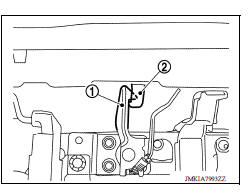
- Remove radiator upper seal clips and then remove upper clip from radiator side seal (RH). Refer to DLK "Exploded View".
- Remove hood lock secondary control nuts and hood lock secondary control.
INSTALLATION
Installation is in the reverse order of removal.
CAUTION: After installation, perform hood lock control inspection. Refer to DLK "Inspection".
Inspection
NOTE: If the hood lock cable is bent or deformed, replace it.
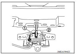
1. Check that secondary latch (1) is properly engaged with secondary striker (2) with hood's own weight.
2. Check that primary latch (1) is securely engaged with primary striker (2) when hood is dropped with hood's own weight from approximately 200 mm (7.9 in) height.
3. While operating the hood lock/fuel filler door release handle assembly, carefully check that the front end of hood is raised by approximately 20.0 mm (0.79 in). Also check that hood lock/fuel filler door release handle assembly returns to the original position.
4. Check that hood lock/fuel filler door release handle assembly operates at 49 N (5.0 kg-f, 11.0 lb-f) or below.
5. Install so that static the hood is 300 - 490 N (31.0 - 50.0 kg-f, 67.4 - 110.2 lb-f).
NOTE:
- Do not exert vertical force on right side and left side of hood lock.
- Do not press simultaneously both sides.
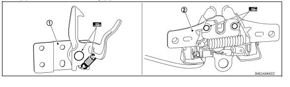
6. Check the hood lock lubrication condition. If necessary, apply a suitable multi-purpose grease to secondary latch (1) and hood lock assembly (2).
FRONT DOOR LOCK
Exploded View
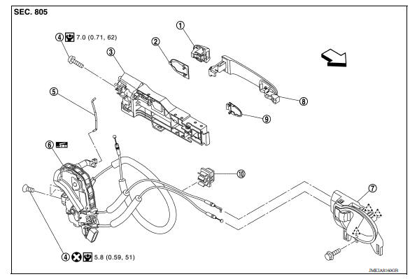
1. Door key cylinder assembly (driver
side)
Outside handle escutcheon (passenger
side)
2. Rear gasket 3. Outside handle bracket
4. Bolt 5. Door key cylinder rod (driver side) 6. Door lock assembly
7. Inside handle 8. Outside handle 9. Front gasket
10. Clip  Pawl
Pawl  Front
Front
 Hood lock control cable
HOOD LOCK CONTROL CABLE : Removal and Installation REMOVAL Disconnect hood lock control cable assembly from hood lock assembly. Refer to DLK "HOOD LOCK : Removal and Installation&quo ...
Door lock
DOOR LOCK : Removal and Installation REMOVAL Remove inside handle. Refer to DLK "INSIDE HANDLE : Removal and Installation". Remove outside handle. Refer to DLK "OUTSIDE HANDLE ...
Other materials:
Exhaust manifold
Exploded View
1. Exhaust manifold cover 2. Harness bracket 3. Airfuel ratio sensor 1 4.
Exhaust manifold stay 5. Heat insulator 6. Exhaust manifold 7. Exhaust manifold
cover 8. Gasket
: Engine front
Removal and Installation
REMOVAL
Remove air duct (inlet), air duct and air cleaner as ...
How to select piston and bearing
Description
Selection points
Selection parts
Selection items
Selection methods
Between cylinder block and
crankshaft
Main bearing
Main bearing grade (bearing
thickness)
Determined by match of cylinder
block bearing housing
grade (inner diameter of housi ...
Categories
- Manuals Home
- Nissan Versa Owners Manual
- Nissan Versa Service Manual
- Video Guides
- Questions & Answers
- External Resources
- Latest Updates
- Most Popular
- Sitemap
- Search the site
- Privacy Policy
- Contact Us

0.0047