Nissan Versa (N17): U1263 USB
DTC Logic
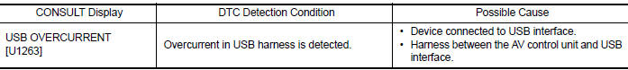
DTC DETECTION LOGIC
DTC CONFIRMATION PROCEDURE
1.PERFORM SELF DIAGNOSTIC RESULT
1. If there is a device connected to the USB interface, disconnect it.
2. Turn ignition switch ON and wait for 2 seconds or more.
3. Perform Self Diagnostic Result for MULTI AV.
Is DTC U1263 displayed?
YES >> Refer to AV "Diagnosis Procedure".
NO >> Inspection End.
Diagnosis Procedure
1.CHECK USB INTERFACE HARNESS
Visually inspect USB interface harness. Refer to AV "Removal and Installation".
Is the inspection result normal?
YES >> GO TO 2.
NO >> Replace USB interface harness. Refer to AV "Removal and Installation".
2.CHECK USB INTERFACE HARNESS
Check USB interface harness. Refer to AV "Diagnosis Procedure".
Is the inspection result normal?
YES >> Replace AV control unit. Refer to AV "Removal and Installation".
NO >> Replace USB interface harness. Refer to AV "Removal and Installation".
 U1258 Satellite radio antenna
DTC Logic DTC DETECTION LOGIC Diagnosis Procedure Regarding Wiring Diagram information, refer to AV "Wiring Diagram". 1.SATELLITE ANTENNA INSPECTION Visually inspect ...
U1264 Antenna AMP
DTC Logic DTC DETECTION LOGIC Diagnosis Procedure Regarding Wiring Diagram information, refer to AV "Wiring Diagram". 1.ANTENNA AMP. INSPECT ...
Other materials:
Standard maintenance
The following tables show the standard maintenance
schedule. Depending upon weather and
atmospheric conditions, varying road surfaces,
individual driving habits and vehicle usage, additional
or more frequent maintenance may be required.
After 120,000 miles
(192,000 km)/144 months, continue m ...
P1148 closed loop control
DTC Logic
DTC DETECTION LOGIC
NOTE:
DTC P1148 is displayed with DTC for A/F sensor 1.
When the DTC is detected, perform the trouble diagnosis of DTC corresponding to
A/F sensor 1.
DTC No.
Trouble diagnosis
(Trouble diagnosis content)
DTC detecting condition
Possible cause ...
Categories
- Manuals Home
- Nissan Versa Owners Manual
- Nissan Versa Service Manual
- Video Guides
- Questions & Answers
- External Resources
- Latest Updates
- Most Popular
- Sitemap
- Search the site
- Privacy Policy
- Contact Us

0.0048