Nissan Versa (N17): U1264 Antenna AMP
DTC Logic
DTC DETECTION LOGIC
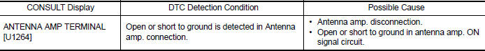
Diagnosis Procedure
Regarding Wiring Diagram information, refer to AV "Wiring Diagram".
1.ANTENNA AMP. INSPECTION
Visually inspect the antenna base (antenna amp.) and antenna feeder. Refer to AV "Feeder Layout".
Is inspection result normal?
YES >> GO TO 2.
NO >> Repair or replace malfunctioning components.
2.CHECK CONTINUITY BETWEEN AV CONTROL UNIT AND ANTENNA BASE
1. Turn ignition switch OFF.
2. Disconnect AV control unit connector M102 and antenna base connector M351.
3. Check continuity between AV control unit connector M102 and antenna base
connector M351.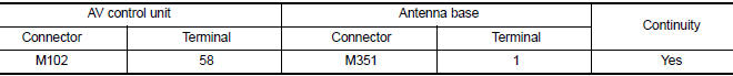
4. Check continuity between AV control unit connector M102 and ground.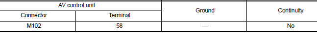
Is the inspection result normal?
YES >> GO TO 2.
NO >> Repair or replace harness or connectors.
3.CHECK AV CONTROL UNIT VOLTAGE
1. Connect AV control unit connector M102.
2. Turn ignition switch ON.
3. Check voltage between AV control unit connector M102 and ground.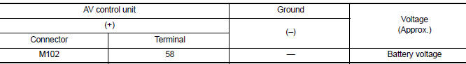
Is the inspection result normal?
YES >> Replace antenna base. Refer to AV "Removal and Installation".
NO >> Replace AV control unit. Refer to AV "Removal and Installation".
 U1263 USB
DTC Logic DTC DETECTION LOGIC DTC CONFIRMATION PROCEDURE 1.PERFORM SELF DIAGNOSTIC RESULT 1. If there is a device connected to the USB interface, disc ...
U12AA Configuration error
DTC Logic DTC DETECTION LOGIC CONSULT Display DTC Detection Condition Possible Cause Configuration Error [U12AA] AV control unit is not properly configured or configurati ...
Other materials:
Remote keyless entry system (if so equipped)
WARNING
Radio waves could adversely affect
electric medical equipment. Those who
use a pacemaker should contact the
electric medical equipment manufacturer
for the possible influences before
use.
The remote keyless entry key fob transmits
radio waves when the buttons are
pressed. ...
Oil pan
Exploded View
1. Transaxle assembly 2. Oil pan gasket 3. Magnet
4. Oil pan 5. Overflow tube 6. Drain plug gasket
7. Drain plug 8. Oil pan fitting bolt
Removal and Installation
REMOVAL
Remove the drain plug and overflow tube, and then drain the ATF.
WARNING:
A/T fluid can splash ...
Categories
- Manuals Home
- Nissan Versa Owners Manual
- Nissan Versa Service Manual
- Video Guides
- Questions & Answers
- External Resources
- Latest Updates
- Most Popular
- Sitemap
- Search the site
- Privacy Policy
- Contact Us

0.0049