Nissan Versa (N17): Oil pan
Exploded View
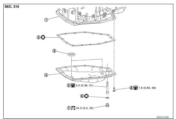
1. Transaxle assembly 2. Oil pan gasket 3. Magnet 4. Oil pan 5. Overflow tube 6. Drain plug gasket 7. Drain plug 8. Oil pan fitting bolt
Removal and Installation
REMOVAL
- Remove the drain plug and overflow tube, and then drain the ATF.
WARNING: A/T fluid can splash when draining, use safety glasses to protect eyes.
- Remove the drain plug gasket from the drain plug.
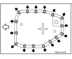
- Remove the oil pan bolts (
 ),
and then remove the oil pan and
oil pan gasket.
),
and then remove the oil pan and
oil pan gasket.
 : Front
4. Remove the magnets from the oil pan.
INSTALLATION
Installation is in the reverse order of removal.
CAUTION:
- Do not reuse oil pan gasket and drain plug gasket.
- Do not reuse oil pan bolts.
- Completely remove all moisture, oil, old gasket, etc. from the oil pan gasket mating surface of transaxle case and oil pan.
- When installing the overflow tube, be sure to tighten to the specified torque. If it is not tightened to the specified torque, the tube may be damaged.
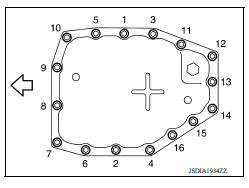
- When the oil pan is installed, temporarily tighten oil pan bolts, then tighten the oil pan bolts to specification in the order shown.
 : Front
Inspection and Adjustment
INSPECTION AFTER REMOVAL
Check oil pan for foreign material.
- If a large amount of worn material is found, clutch plate may be worn.
- If iron powder is found, bearings, gears, or clutch plates may be worn.
- If aluminum powder is found, bushing may be worn, or chips or burrs of aluminum casting parts may enter.
Check points where wear is found in all cases.
INSPECTION AFTER INSTALLATION
Check for A/T fluid leakage. Refer to TM "Inspection".
ADJUSTMENT AFTER INSTALLATION
Check the A/T fluid level. Refer to TM "Adjustment".
 TCM
TCM
Exploded View 1. TCM 2. Bracket 3. Clips Front Removal and Installation NOTE: When replacing the TCM and transaxle assembly as a set, replace the transaxle assembly first and then re ...
Output speed sensor
Exploded View 1. Output speed sensor 2. O-ring 3. Transaxle assembly Front Removal and Installation REMOVAL Remove the front LH wheel and tire. Disconnect the harness connector from o ...
Other materials:
Head restraints/headrests
WARNING
Head restraints/headrests supplement
the other vehicle safety systems. They may
provide additional protection against injury
in certain rear end collisions. Adjustable
head restraints/headrests must be
adjusted properly, as specified in this section.
Check the adjustment after someo ...
Vehicle identification
Vehicle identification number (VIN) plate
The vehicle identification number (VIN) plate is
attached as shown. This number is the identification
for your vehicle and is used in the vehicle
registration.
Vehicle identification number (chassis number)
The vehicle identification number i ...
Categories
- Manuals Home
- Nissan Versa Owners Manual
- Nissan Versa Service Manual
- Video Guides
- Questions & Answers
- External Resources
- Latest Updates
- Most Popular
- Sitemap
- Search the site
- Privacy Policy
- Contact Us

0.0053