Nissan Versa (N17): Washer fluid level switch circuit
Description
Transmits the washer fluid level switch signal to the combination meter.
Diagnosis Procedure
Regarding Wiring Diagram information, refer to MWI "Wiring Diagram".
1.CHECK WASHER FLUID LEVEL SWITCH SIGNAL CIRCUIT
1. Turn ignition switch OFF.
2. Disconnect combination meter connector and washer fluid level switch connector.
3. Check continuity between combination meter harness connector M24 terminal
11 and washer fluid level
switch harness connector E50 terminal 1. 
4. Check continuity between combination meter harness connector M24 terminal
11 and ground. 
Is the inspection result normal?
YES >> GO TO 2.
NO >> Repair or replace harness or connector.
2.CHECK WASHER FLUID LEVEL SWITCH GROUND CIRCUIT
Check continuity between washer fluid level switch harness connector E50
terminal 2 and ground. 
Is the inspection result normal?
YES >> Inspection End.
NO >> Repair or replace harness or connector.
Component Inspection
1.CHECK WASHER FLUID LEVEL SWITCH
Check continuity between washer fluid level switch terminals 1 and 2. 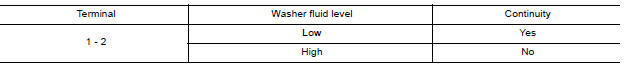
Is the inspection result normal?
YES >> Inspection End.
NO >> Replace washer fluid level switch. Refer to WW "Exploded View".
SYMPTOM DIAGNOSIS
 Fuel level sensor signal circuit
Description The fuel level sensor unit and fuel pump detects the approximate fuel level in the fuel tank and transmits the fuel level signal to the combination meter. ...
The fuel gauge indicator does not
operate
Description Fuel gauge will not indicate from a certain position. Diagnosis Procedure 1.CHECK COMBINATION METER INPUT SIGNAL 1. Select METER/M&A on CONSULT. 2. Using "DATA MONITOR, compare ...
Other materials:
Cold weather driving
Freeing a frozen door lock
To prevent a door lock from freezing, apply deicer
through the key hole. If the lock becomes
frozen, heat the key before inserting it into the key
hole, or use the remote keyless entry key fob or
the NISSAN Intelligent Key.
Antifreeze
In the winter when it is antic ...
EVAP canister
Exploded View
1. EVAP control system pressure sensor 2. O-ring 3. EVAP canister
4. Hose clamp 5. EVAP canister purge hose 6. EVAP vent line
7. O-ring 8. EVAP canister vent control valve 9. EVAP canister vent control
valve
hose
A. Mount to vehicle bracket
Removal and Installation
NOTE: ...
Categories
- Manuals Home
- Nissan Versa Owners Manual
- Nissan Versa Service Manual
- Video Guides
- Questions & Answers
- External Resources
- Latest Updates
- Most Popular
- Sitemap
- Search the site
- Privacy Policy
- Contact Us

0.0057