
Nissan Versa (N17): C1155 BR Fluid level low
DTC Logic
DTC DETECTION LOGIC 
DTC CONFIRMATION PROCEDURE
1.CHECK SELF-DIAGNOSIS RESULTS
Check the self-diagnosis results. 
Is above displayed on the self-diagnosis display?
YES >> Proceed to diagnosis procedure. Refer to BRC "Diagnosis Procedure".
NO >> Inspection End.
Diagnosis Procedure
Regarding Wiring Diagram information, refer to BRC "Wiring Diagram".
NOTE: Check brake fluid level in brake reservoir tank before starting inspection.
1.CONNECTOR INSPECTION
- Turn ignition switch OFF.
- Disconnect combination meter and brake fluid level switch connectors.
- Check connectors and terminals for deformation, disconnection, looseness or damage.
Is the inspection result normal?
YES >> GO TO 2
NO >> Repair or replace as necessary.
2.CHECK BRAKE FLUID LEVEL SWITCH
Perform the brake fluid level switch component inspection. Refer to BRC"Component Inspection".
Is the inspection result normal?
YES >> GO TO 3
NO >> Replace brake fluid level switch. Refer to BR "Exploded View".
3.CHECK BRAKE FLUID LEVEL SWITCH HARNESS
- Check continuity between combination meter connector and brake fluid
level switch connector E40 terminal
1.

2. Check continuity between combination meter
connector and ground. 
Is the inspection result normal?
YES >> GO TO 4
NO >> Repair or replace malfunctioning components.
4.CHECK BRAKE FLUID LEVEL SWITCH GROUND CIRCUIT
Check continuity between brake fluid level switch connector E40 terminal 2
and ground. 
Is the inspection result normal?
YES >> Replace ABS actuator and electric unit (control unit). Refer to BRC "Removal and Installation"
NO >> Repair or replace malfunctioning components.
Component Inspection
1.CHECK BRAKE FLUID LEVEL SWITCH
- Turn ignition switch OFF.
- Disconnect brake fluid level switch connector.
- Check continuity between brake fluid level switch terminals 1
and 2.

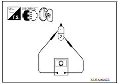
Is the inspection result normal?
YES >> Inspection End.
NO >> Replace brake fluid level switch. Refer to BR "Exploded View".
 C1145, C1146 Yaw rate/side/decel g
sensor
C1145, C1146 Yaw rate/side/decel g
sensor
DTC Logic DTC DETECTION LOGIC DTC CONFIRMATION PROCEDURE 1.CHECK SELF DIAGNOSTIC RESULT With CONSULT. Turn ignition switch OFF to ON. Perform self diagnostic result. Is ...

Other materials:
Seats
WARNING
Do not ride in a moving vehicle when
the seatback is reclined. This can be
dangerous. The shoulder belt will not
be against your body. In an accident,
you could be thrown into it and receive
neck or other serious injuries. You
could also slide under the lap belt and
recei ...
EVAP control system pressure sensor
Exploded View
1. EVAP control system pressure sensor 2. O-ring 3. EVAP canister
Removal and Installation
NOTE:
The EVAP canister system pressure sensor can be removed without removing the
EVAP canister.
REMOVAL
Remove the EVAP canister protector cover.
Disconnect EVAP canister purg ...
Categories
- Manuals Home
- Nissan Versa Owners Manual
- Nissan Versa Service Manual
- Video Guides
- Questions & Answers
- External Resources
- Latest Updates
- Most Popular
- Sitemap
- Search the site
- Privacy Policy
- Contact Us

0.0135