Nissan Versa (N17): Electrical load signal
Description
The electrical load signal (Headlamp switch signal, rear window defogger switch signal, etc.) is transferred to ECM through the CAN communication line.
Component Function Check
1.CHECK REAR WINDOW DEFOGGER SWITCH FUNCTION
- Turn ignition switch ON.
- Select "DATA MONITOR" mode with CONSULT.
- Select "LOAD SIGNAL" and check indication under the following
conditions.
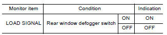
Is the inspection result normal?
YES >> GO TO 2.
NO >> Go to EC, "Diagnosis Procedure".
2.CHECK LIGHTING SWITCH FUNCTION
Check "LOAD SIGNAL" indication under the following conditions.
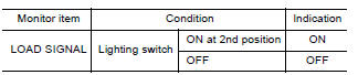
Is the inspection result normal?
YES >> GO TO 3.
NO >> Go to EC, "Diagnosis Procedure".
3.CHECK HEATER FAN CONTROL SWITCH FUNCTION
Select "HEATER FAN SW" and check indication under the following conditions
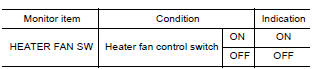
Is the inspection result normal?
YES >> INSPECTION END
NO >> Go to EC, "Diagnosis Procedure".
Diagnosis Procedure
1.INSPECTION START
Confirm the malfunctioning circuit (rear window defogger, headlamp or heater fan). Refer to EC, "Component Function Check".
Which circuit is related to the incident?
Rear window defogger>>GO TO 2
Headlamp>>GO TO 3.
Heater fan>>GO TO 4.
2.CHECK REAR WINDOW DEFOGGER SYSTEM
Perform trouble diagnosis of rear window defogger system. Refer to DEF, "Work Flow".
>> INSPECTION END
3.CHECK HEADLAMP SYSTEM
Perform trouble diagnosis of headlamp system. Refer to EXL, "Work Flow".
>> INSPECTION END
4.CHECK AIR CONDITIONING SYSTEM
Perform trouble diagnosis of air conditioning system. Refer to HA, "Workflow".
>> INSPECTION END
 Cooling fan
Other materials:
Fuel efficient driving tips
Follow these easy-to-use Fuel Efficient Driving
Tips to help you achieve the most fuel economy
from your vehicle.
1. Use Smooth Accelerator and Brake
Pedal Application
Avoid rapid starts and stops.
Use smooth, gentle accelerator and
brake application whenever possible.
Maintain constan ...
Towing a trailer
Flat towing
Do not tow a trailer with your vehicle.
Towing your vehicle with all four wheels on the
ground is sometimes called flat towing. This
method is sometimes used when towing a vehicle
behind a recreational vehicle, such as a motor
home.
CAUTION
Failure to follow these guidelines c ...
Categories
- Manuals Home
- Nissan Versa Owners Manual
- Nissan Versa Service Manual
- Video Guides
- Questions & Answers
- External Resources
- Latest Updates
- Most Popular
- Sitemap
- Search the site
- Privacy Policy
- Contact Us

0.0079