Nissan Versa (N17): Diagnosis and repair work flow
Work Flow
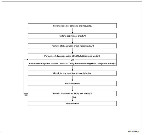
OVERALL SEQUENCE
*1 SRC "Diagnosis Description" *2 SRC "SRS Operation Check" *3 SRC "Trouble Diagnosis with CONSULT" *4 SRC "Trouble Diagnosis without CONSULT"
DETAILED WORK FLOW
1.CUSTOMER INFORMATION
Get detailed information from the customer about the symptom.
>> GO TO 2
2.PRELIMINARY CHECK
Perform preliminary check. Refer to SRC "Diagnosis Description".
>> GO TO 3
3.SRS OPERATION CHECK (USER MODE)
Perform SRS operation check in User Mode. Refer to SRC "SRS Operation Check".
>> GO TO 4
4.SELF-DIAGNOSIS (DIAGNOSIS MODE)
Perform SELF-DIAGNOSIS. Refer to SRC "Trouble Diagnosis with CONSULT"or SRC"Trouble Diagnosis without CONSULT".
>> GO TO 5
5.TECHNICAL SERVICE BULLETINS
Check for technical service bulletins.
>> GO TO 6
6.REPLACE PART
Replace the malfunctioning part.
>> GO TO 7
7.FINAL CHECK
Check SRS using Diagnosis Mode and User Mode.
Does Diagnosis Mode and User Mode indicate SRS normal?
YES >> Inspection End.
NO >> GO TO 4
 Diagnosis sensor unit
DTC Index DIAGNOSTIC CODE CHART NOTE: Follow the procedures in numerical order when repairing malfunctioning parts. Confirm whether malfunction is eliminated using air bag warning lamp or CONSU ...

Other materials:
Trunk lid hinge
TRUNK LID HINGE : Removal and Installation
REMOVAL
1. Remove harness clips (A) from trunk lid hinge (RH only) (1).
2. Remove trunk lid assembly. Refer to DLK "TRUNK LID ASSEMBLY : Removal and
Installation".
3. Remove torsion bar. Refer to DLK "TORSION BAR : Removal and Insta ...
A-BAG Branch line circuit
Diagnosis Procedure
WARNING:
Always observe the following items for preventing accidental activation.
Before servicing, turn ignition switch OFF, disconnect battery
negative terminal, and wait 3 minutes
or more. (To discharge backup capacitor.)
Never use unspecified tester or other meas ...
Categories
- Manuals Home
- Nissan Versa Owners Manual
- Nissan Versa Service Manual
- Video Guides
- Questions & Answers
- External Resources
- Latest Updates
- Most Popular
- Sitemap
- Search the site
- Privacy Policy
- Contact Us

0.0048