Nissan Versa (N17): EVAP canister
Exploded View
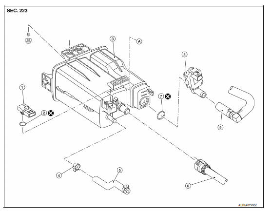
1. EVAP control system pressure sensor 2. O-ring 3. EVAP canister 4. Hose clamp 5. EVAP canister purge hose 6. EVAP vent line 7. O-ring 8. EVAP canister vent control valve 9. EVAP canister vent control valve hose A. Mount to vehicle bracket
Removal and Installation
NOTE: The EVAP canister vent control valve and EVAP canister system pressure sensor can be removed without removing the EVAP canister.
REMOVAL
- Remove the EVAP canister protector cover.
- Disconnect the harness connectors from the EVAP control system pressure sensor and the EVAP canister vent control valve.
- Disconnect the EVAP canister purge hose, the EVAP vent line, and the EVAP canister vent control valve hose.
- Remove the EVAP canister bolt.
- Remove the EVAP canister from the vehicle.
INSTALLATION
Installation is in the reverse order of removal.
CAUTION: Do not reuse O-rings.
Inspection
Check EVAP canister as follows:
- Block port (B).
- Blow air into port (A) and check that it flows freely out of port (C).
- Release blocked port (B).
- Apply vacuum pressure to port (B) and check that vacuum pressure exists at the ports (A) and (C).
- Block port (A) and (B).
- Apply pressure to port (C) and check that there is no leakage.
 Fuel tank
Exploded View 1. Fuel tank 2. Fuel tank mounting band (RH) 3. Fuel tank mounting band (LH) 4. Clamp 5. Fuel filler hose 6. Fuel filler tube 7. Grommet 8. Fuel filler cap 9. Clamp 10. Vent hose ...
EVAP canister filter
Exploded View 1. EVAP canister vent control valve hose 2. Canister drain hose 3. EVAP canister filter Front Removal and Installation REMOVAL Remove the EVAP canister protector cover. ...
Other materials:
Steering wheel
Tilt operation
Push the lock lever 1 down and adjust the
steering wheel up or down 2 to the desired
position.
Pull the lock lever 1 up to lock the steering
wheel in place.
WARNING
Do not adjust the steering wheel while
driving. You could lose control of your
vehicle and cause an accid ...
Bluetooth Hands-Free Phone System without Navigation System (Type A) (if so
equipped)
WARNING
Use a phone after stopping your vehicle
in a safe location. If you have to use a
phone while driving, exercise extreme
caution at all times so full attention may
be given to vehicle operation.
If you are unable to devote full attention
to vehicle operation while talking on
...
Categories
- Manuals Home
- Nissan Versa Owners Manual
- Nissan Versa Service Manual
- Video Guides
- Questions & Answers
- External Resources
- Latest Updates
- Most Popular
- Sitemap
- Search the site
- Privacy Policy
- Contact Us

0.0056