Nissan Versa (N17): Exhaust valve timing control
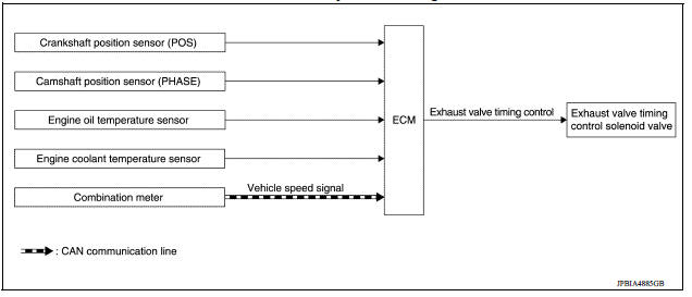
Exhaust valve timing control : system diagram
Exhaust valve timing control : system description
INPUT/OUTPUT SIGNAL CHART
| Sensor | Input signal to ECM | ECM function | Actuator |
| Crankshaft position sensor (POS) | Engine speed*1 Piston position | Exhaust valve timing control | Exhaust valve timing control solenoid valve |
| Camshaft position sensor (PHASE) | |||
| Engine oil temperature sensor | Engine oil temperature | ||
| Engine coolant temperature sensor | Engine coolant temperature | ||
| Combination meter | Vehicle speed*2 |
*1: ECM determines the start signal status by the signals of engine speed and battery voltage.
*2: This signal is sent to the ECM through CAN communication line.
SYSTEM DESCRIPTION
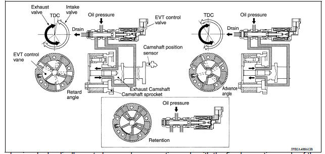
This mechanism hydraulically controls cam phases continuously with the fixed operating angle of the exhaust valve.
The ECM receives signals such as crankshaft position, camshaft position, engine speed, engine oil temperature and engine coolant temperature. Then, the ECM sends ON/OFF pulse duty signals to the exhaust valve timing (EVT) control solenoid valve depending on driving status. This makes it possible to control the shut/ open timing of the exhaust valve to increase engine torque and output in a range of high engine speed.
 Intake valve timing control
Intake valve timing control : System Diagram Intake valve timing control : system description INPUT/OUTPUT SIGNAL CHART Sensor Input signal to ECM ECM function Actuator ...
Engine protection control at low engine oil pressure
Engine protection control at low engine oil pressure : system diagram Engine protection control at low engine oil pressure : system description INPUT/OUTPUT SIGNAL CHART Sensor Inpu ...
Other materials:
Precautions
Precaution for Supplemental Restraint System
(SRS) "AIR BAG" and "SEAT BELT PRE-TENSIONER"
The Supplemental Restraint System such as "AIR BAG" and "SEAT BELT PRE-TENSIONER",
used along
with a front seat belt, helps to reduce the risk or severity of injury to the
driver and ...
The braking distance is long
Diagnosis Procedure
CAUTION:
The stopping distance on slippery road surfaces might be longer with the ABS
operating than when
the ABS is not operating.
1.CHECK ABS FUNCTION
Turn ignition switch OFF.
Disconnect ABS actuator and electric unit (control unit) connector to
deactivate ABS ...
Categories
- Manuals Home
- Nissan Versa Owners Manual
- Nissan Versa Service Manual
- Video Guides
- Questions & Answers
- External Resources
- Latest Updates
- Most Popular
- Sitemap
- Search the site
- Privacy Policy
- Contact Us

0.011