Nissan Versa (N17): Lock-up control
LOCK-UP CONTROL : System Description
SYSTEM DIAGRAM
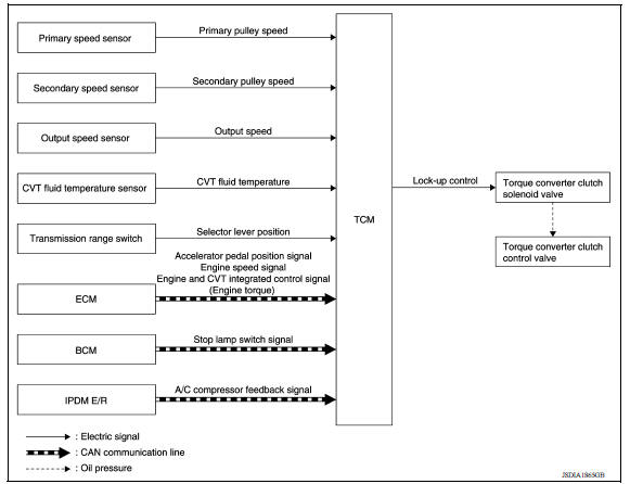
DESCRIPTION
- Controls for improvement of the transmission efficiency by engaging the torque converter clutch in the torque converter and eliminating slip of the converter. Achieves comfortable driving with slip control of the torque converter clutch.
- The oil pressure feed circuit for the torque converter clutch piston chamber is connected to the torque converter clutch control valve. The torque converter clutch control valve is switched by the torque converter clutch solenoid valve with the signal from TCM. This controls the oil pressure circuit, which is supplied to the torque converter clutch piston chamber, to the release side or engagement side.
- If the CVT fluid temperature is low or the vehicle is in fail-safe mode due to malfunction, lock-up control is prohibited.
Lock-up engagement
In lock-up engagement, the torque converter clutch solenoid valve makes the torque converter clutch control valve locked up to generate the lock-up apply pressure. This pushes the torque converter clutch piston for engagement.
Lock-up release condition
In lock-up release, the torque converter clutch solenoid valve makes the torque converter clutch control valve non-locked up to drain the lock-up apply pressure. This does not engage the torque converter clutch piston.
 Shift control
SHIFT CONTROL : System Description SYSTEM DIAGRAM DESCRIPTION To select the gear ratio that can give the driving force to meet driver's intent or vehicle situation, the vehicle driving con ...
Idle neutral control
IDLE NEUTRAL CONTROL : System Description SYSTEM DIAGRAM DESCRIPTION If a driver has no intention of starting the vehicle in D position, TCM operates the low brake solenoid valve and control ...
Other materials:
Power steering fluid
Check the fluid level in the reservoir.
The fluid level should be checked when the fluid
is cold at fluid temperatures of 32 to 86ºF (0 to
30ºC). The fluid level can be checked with the
level gauge which is attached to the cap. To
check the fluid level, remove the cap. The fluid ...
Body side welt
BODY SIDE WELT : Removal and Installation
CAUTION:
Do not excessively pull or stretch body side welts.
FRONT BODY SIDE WELT
Removal
Remove dash side finisher. Refer to INT "DASH SIDE FINISHER : Removal
and Installation".
Remove center pillar lower finisher. Refer to INT &quo ...
Categories
- Manuals Home
- Nissan Versa Owners Manual
- Nissan Versa Service Manual
- Video Guides
- Questions & Answers
- External Resources
- Latest Updates
- Most Popular
- Sitemap
- Search the site
- Privacy Policy
- Contact Us

0.0073