Nissan Versa (N17): S connector circuit
Description
The starter motor magnetic switch is supplied with power when the ignition switch is turned to the START position while the selector lever is in the P (Park) or N (Neutral) position.
Diagnosis Procedure
Regarding Wiring Diagram information, refer to STR, "Wiring Diagram - With Intelligent Key System" or STR, "Wiring Diagram - Without Intelligent Key System".
CAUTION: Perform diagnosis under the condition that engine cannot start by the following procedure.
- Remove fuel pump fuse.
- Crank or start the engine (where possible) until the fuel pressure is released.
1.CHECK "S" CONNECTOR CIRCUIT
- Turn ignition switch OFF.
- Disconnect starter motor connector.
- Shift selector lever to "P" (Park) or "N" (Neutral) position.
- Check voltage between starter motor harness connector F28 and ground.
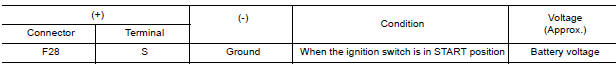
Is the inspection result normal?
YES >> "S" circuit is OK. Further inspection is necessary. Refer to STR, "Work Flow (With GR8-1200 NI)" or STR, "Work Flow (Without GR8-1200 NI)".
NO >> GO TO 2.
2.CHECK HARNESS CONTINUITY (OPEN CIRCUIT)
- Disconnect IPDM E/R connector.
- Check continuity between starter motor harness connector F28 and the
IPDM E/R harness connector
E43.
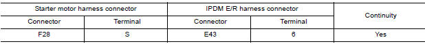
- Check continuity between starter motor connector F28 terminal S and
ground.

Is the inspection result normal?
YES >> Further inspection is necessary. Refer to STR, "Work Flow (With GR8-1200 NI)" or STR, "Work Flow (Without GR8-1200 NI)".
NO >> Repair or replace the harness or connectors.
STARTING SYSTEM
Symptom Table
| Symptom | Reference |
| No normal cranking | Refer to STR, "Work Flow (With GR8-1200 NI)" or STR, "Work Flow (Without GR8-1200 NI)". |
| Starter motor does not rotate |
 B terminal circuit
Description Terminal "B" is constantly supplied with battery power. Diagnosis Procedure Regarding Wiring Diagram information, refer to STR, "Wiring Diagram - With Intelligent Key System&quo ...

Other materials:
Vehicle jerks during VDC/TCS/ABS
control
Diagnosis Procedure
1.SYMPTOM CHECK
Check if the vehicle jerks during VDC/TCS/ABS control.
Is the inspection result normal?
YES >> Inspection End.
NO >> GO TO 2
2.CHECK SELF DIAGNOSTIC RESULT
Perform self diagnostic result of ABS actuator and electric unit (control
unit). Refe ...
Component parts Component parts Component parts
Component Parts Location
1. BCM (view with instrument panel removed)
2. ECM 3. IPDM E/R
4. Meter 5. Security indicator lamp 6. CVT shift selector (park position
switch) (view with center console removed)
7. Stop lamp switch 8. Push button ignition switch 9 NATS antenna amp.
10. Remot ...
Categories
- Manuals Home
- Nissan Versa Owners Manual
- Nissan Versa Service Manual
- Video Guides
- Questions & Answers
- External Resources
- Latest Updates
- Most Popular
- Sitemap
- Search the site
- Privacy Policy
- Contact Us

0.005