Nissan Versa (N17): B2267 Engine speed
Description
The engine speed signal is transmitted from ECM to the combination meter via CAN communication.
DTC Logic
DTC DETECTION LOGIC 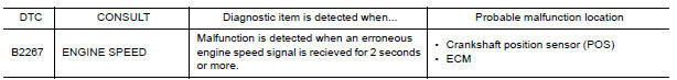
Diagnosis Procedure
1.CHECK COMBINATION METER INPUT SIGNAL
1. Start engine and select METER/M&A on CONSULT.
2. Using TACHO METER on DATA MONITOR, compare the value of DATA MONITOR with tachometer of combination meter. Tachometer and DATA MONITOR indications should be close.
Is the inspection result normal?
YES >> Perform ECM self-diagnosis. Refer to EC "CONSULT Function".
NO >> Replace combination meter. Refer to MWI "Removal and Installation".
B2268 WATER TEMP
Description
The engine coolant temperature signal is transmitted from ECM to the combination meter via CAN communication.
DTC Logic
DTC DETECTION LOGIC 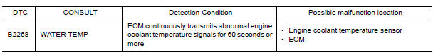
Diagnosis Procedure
1.PERFORM SELF-DIAGNOSIS OF ECM
Perform "Self Diagnosis Result" of "ENGINE", and repair or replace malfunctioning parts.
>> Refer to EC "CONSULT Function".
 DTC B2205 Vehicle speed circuit
Description The ABS actuator and electric unit (control unit) provides a vehicle speed signal to the combination meter via CAN communication lines. DTC Logic &n ...

Other materials:
Engine control system
ENGINE CONTROL SYSTEM : Component Parts Location
1. Mass air flow sensor
(with intake air temperature sensor)
2. Electric throttle control actuator
(with built in throttle position sensor
and throttle control motor)
3. EVAP canister purge volume control
solenoid valve
4. Cooling fan mot ...
Brake pedal
Inspection and Adjustment
INSPECTION
Brake Pedal Height
Check the height (H1) between the dash lower panel (1) and the
brake pedal upper surface.
(H1) : Refer to BR "Brake Pedal".
CAUTION:
Remove the floor trim.
Stop Lamp Switch
Check the clearance (C) among the brake ped ...
Categories
- Manuals Home
- Nissan Versa Owners Manual
- Nissan Versa Service Manual
- Video Guides
- Questions & Answers
- External Resources
- Latest Updates
- Most Popular
- Sitemap
- Search the site
- Privacy Policy
- Contact Us

0.0049