Nissan Versa (N17): Brake pedal
Inspection and Adjustment
INSPECTION
Brake Pedal Height
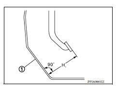
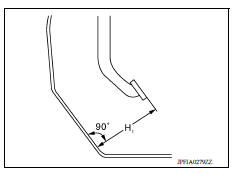
Check the height (H1) between the dash lower panel (1) and the brake pedal upper surface.
(H1) : Refer to BR "Brake Pedal".
CAUTION: Remove the floor trim.
Stop Lamp Switch
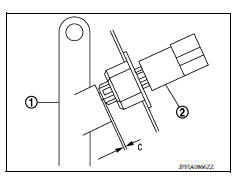
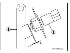
Check the clearance (C) among the brake pedal lever (1) and the stop lamp switch (2) threaded end.
(C) : Refer to BR "Brake Pedal".
CAUTION: The stop lamp must turn off when the brake pedal is released.
ASCD Cancel Switch
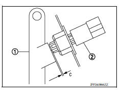
Check the clearance (C) among the brake pedal lever (1) and the ASCD cancel switch (2) threaded end.
(C) : Refer to BR "Brake Pedal".
CAUTION: The stop lamp must turn off when the brake pedal is released.
Brake Pedal Play
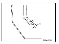
Press the brake pedal. Check the brake pedal play (A) (stroke until fluid pressure occurs).
(A) : Refer to BR "Brake Pedal".
Depressed Brake Pedal Height
Check the height between the dash lower panel (1) and the brake pedal upper surface (H2) when depressing the brake pedal at 490 N (50 kg-f, 110 lb-f) while turning engine ON.
(H2) : Refer to BR "Brake Pedal".
CAUTION: Remove the floor trim.

ADJUSTMENT
Brake Pedal Height
- Remove instrument lower panel LH. Refer to IP "Removal and Installation".
- Disconnect the harness connector from stop lamp switch.
- Loosen the stop lamp switch 45 counterclockwise.
- Adjust the brake pedal height with the following procedure.
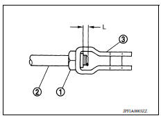
a. Loosen the input rod lock nut (1).
CAUTION: The threaded end of the input rod (2) must project to the inner side (L) of the clevis (3).
b. Rotate the input rod, adjust the brake pedal to the specified height (H1).
(H1) : Refer to BR "Brake Pedal".
c. Tighten the lock nut. Refer to BR "Exploded View".
5. Check the brake pedal play.
Stop Lamp Switch
- Remove instrument lower panel LH. Refer to IP "Removal and Installation".
- Disconnect the harness connector from stop lamp switch.
- Loosen the stop lamp switch 45 counterclockwise.
- Press-fit the stop lamp switch (2) until the stop lamp switch hits the brake pedal lever (1) 45 clockwise while pulling the brake pedal pad slightly.
CAUTION:
- The clearance (C) between the brake pedal lever and stop lamp switch threaded and must be the specified value.
(C) : Refer to BR "Brake Pedal".
- The stop lamp must be turned off when the brake pedal is released.
ASCD Cancel Switch
- Remove instrument lower panel LH. Refer to IP "Removal and Installation".
- Disconnect the harness connector from ASCD cancel switch.
- Loosen the stop lamp switch 45 counterclockwise.
- Press-fit the ASCD cancel switch (2) until the ASCD cancel switch hits the brake pedal lever (1) 45 clockwise while pulling the brake pedal pad slightly.
CAUTION:
- The clearance (C) between the brake pedal lever and ASCD cancel switch threaded and must be the specified value.
(C) : Refer to BR "Brake Pedal".
- The stop lamp must be turned off when the brake pedal is released.
 Precautions
Other materials:
VDC/TCS/ABS
Symptom Table
If ABS warning lamp and SLIP indicator lamp turn ON, perform self-diagnosis.
NOTE:
The ABS does not operate when the speed is 10 km/h (6 MPH) or less.
Under the following conditions, ABS is activated and vibration is
felt when brake pedal is lightly depressed (just place ...
Combination switch
Exploded View
1. Combination switch 2. Combination switch harness connector Front
Removal and Installation
1. Remove the steering wheel. Refer to ST "Removal and Installation".
2. Remove the steering column cover. Refer to IP "Removal and Installation".
3. Remove the com ...
Categories
- Manuals Home
- Nissan Versa Owners Manual
- Nissan Versa Service Manual
- Video Guides
- Questions & Answers
- External Resources
- Latest Updates
- Most Popular
- Sitemap
- Search the site
- Privacy Policy
- Contact Us

0.005