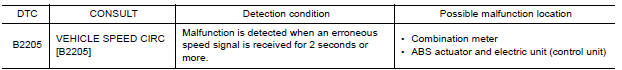
Nissan Versa (N17): DTC B2205 Vehicle speed circuit
Description
The ABS actuator and electric unit (control unit) provides a vehicle speed signal to the combination meter via CAN communication lines.
DTC Logic
Diagnosis Procedure
1.CHECK COMBINATION METER INPUT SIGNAL
1. Start engine and select METER/M&A on CONSULT.
2. Using SPEED METER on DATA MONITOR, compare the DATA MONITOR value with the combination meter speedometer. Speedometer and DATA MONITOR indications should be close.
Is the inspection result normal?
YES >> Perform ABS actuator and electric unit (control unit) self-diagnosis. Refer to BRC "CONSULT Function (ABS)".
NO >> Replace combination meter. Refer to MWI"Removal and Installation".
 U1000 CAN Comm circuit
DTC Logic DTC DETECTION LOGIC Diagnosis Procedure 1.CHECK DTC DETECTION With CONSULT. 1. Turn ignition switch OFF to ON. 2. Perform self diagnostic result. Is DTC U1000 det ...
B2267 Engine speed
Description The engine speed signal is transmitted from ECM to the combination meter via CAN communication. DTC Logic DTC DETECTION LOGIC Diagnosis P ...
Other materials:
Vehicle speed sensing auto lock
operation does not operate
Diagnosis Procedure
1.CHECK AUTOMATIC LOCK/UNLOCK SELECT SETTING IN WORK SUPPORT
Select DOOR LOCK of BCM using CONSULT.
Select AUTOMATIC LOCK/UNLOCK SELECT in WORK SUPPORT mode.
Check AUTOMATIC LOCK/UNLOCK SELECT setting in WORK SUPPORT.
Refer to BCS "DOOR LOCK : CONSULT Function ( ...
Key reminder function does not operate
Diagnosis Procedure
1.CHECK ANTI KEY LOCK IN FUNCTI SETTING IN WORK SUPPORT
Select INTELLIGENT KEY of BCM using CONSULT.
Select ANTI KEY LOCK IN FUNCTI in WORK SUPPORT mode.
Check ANTI KEY LOCK IN FUNCTI setting in WORK SUPPORT.
Refer to BCS "INTELLIGENT KEY : CONSULT Function (BCM ...
Categories
- Manuals Home
- Nissan Versa Owners Manual
- Nissan Versa Service Manual
- Video Guides
- Questions & Answers
- External Resources
- Latest Updates
- Most Popular
- Sitemap
- Search the site
- Privacy Policy
- Contact Us

0.0055