Nissan Versa (N17): Front wiper auto stop signal circuit
Component Function Check
1. CHECK FRONT WIPER (AUTO STOP) SIGNAL
1. Select FR WIPER STOP of BCM (WIPER) data monitor item.
2. Operate the front wiper.
3. Check that FR WIPER STOP changes from ON to OFF according to the wiper
position.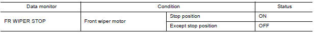
Is the inspection result normal?
YES >> Front wiper auto stop signal circuit is normal.
NO >> Refer to WW "Diagnosis Procedure".
Diagnosis Procedure
Regarding Wiring Diagram information, refer to WW "Wiring Diagram".
1. CHECK FRONT WIPER MOTOR (AUTO STOP) OUTPUT VOLTAGE
1. Turn the ignition switch ON.
2. Check voltage between IPDM E/R harness connector and ground.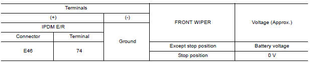
Is the inspection result normal?
YES >> Check for intermittent failure.
NO >> GO TO 2
2. CHECK FRONT WIPER MOTOR (AUTO STOP) SHORT CIRCUIT
1. Turn the ignition switch OFF.
2. Disconnect IPDM E/R and front wiper motor.
3. Check continuity between IPDM E/R harness connector and ground.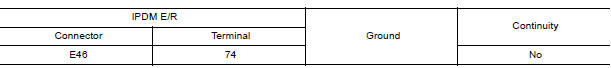
Is the inspection result normal?
YES >> Repair or replace harness.
NO >> GO TO 3.
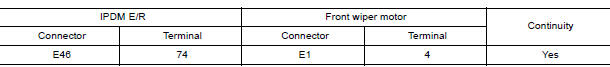
3. CHECK FRONT WIPER MOTOR (AUTO STOP) CIRCUIT CONTINUITY
Check continuity between IPDM E/R harness connector and front wiper motor harness connector.
Is the inspection result normal?
YES >> Replace front wiper motor. Refer to WW "WIPER DRIVE ASSEMBLY : Removal and Installation".
NO >> Repair or replace harness.
 Front wiper motor hi circuit
Front wiper motor ground circuit
Diagnosis Procedure Regarding Wiring Diagram information, refer to WW "Wiring Diagram". 1. CHECK FRONT WIPER MOTOR GROUND CIRCUIT 1. Turn the ignition switch OFF. 2. Disconnect front wip ...
Other materials:
Key interlock cable
Exploded View
1. A/T shift selector assembly 2. Key interlock cable A: Key cylinder
B: Lock plate C: Clip
Removal and Installation
CAUTION:
Always apply the parking brake before performing removal and installation.
REMOVAL
Move the shift selector to the "N" position.
Remove the s ...
Shift lock system
SHIFT LOCK SYSTEM : Component Parts Location
1. Stop lamp switch 2. Shift lock release lever 3. Park position switch
4. Shift lock solenoid
Component
Function
Stop lamp switch
Stop lamp switch turns ON when brake pedal is depressed
Shift lock release lever
Ma ...
Categories
- Manuals Home
- Nissan Versa Owners Manual
- Nissan Versa Service Manual
- Video Guides
- Questions & Answers
- External Resources
- Latest Updates
- Most Popular
- Sitemap
- Search the site
- Privacy Policy
- Contact Us

0.0063