
Nissan Versa (N17): Vehicle security indicator
Description
- Vehicle security indicator is built in combination meter.
- NATS (Nissan Anti-Theft System) condition is indicated by blink or illumination of vehicle security indicator.
Component Function Check
1.CHECK FUNCTION
1. Perform Active Test of THEFT IND in the IMMU mode with CONSULT.
2. Check vehicle security indicator operation. 
Is the inspection result normal?
YES >> Inspection End.
NO >> Refer to SEC "Diagnosis Procedure".
Diagnosis Procedure
Regarding Wiring Diagram information, refer to SEC "Wiring Diagram".
1.SECURITY INDICATOR LAMP ACTIVE TEST
With CONSULT
Check "THEFT IND" in "ACTIVE TEST" of IMMU mode with CONSULT.
Without CONSULT
1. Disconnect BCM.
2. Check voltage between BCM harness connector M18 terminal 23 and ground.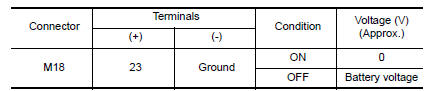
Is the inspection result normal?
YES >> Security indicator lamp is OK.
NO >> GO TO 2
2.SECURITY INDICATOR LAMP CHECK
Check security indicator lamp condition.
Is the inspection result normal?
YES >> GO TO 3
NO >> Replace combination meter. Refer to MWI "Removal and Installation" (type B) or MWI "Removal and Installation" (type A).
3.CHECK HARNESS CONTINUITY
1. Turn ignition switch OFF.
2. Disconnect BCM and security indicator lamp connector.
3. Check continuity between BCM connector M18 terminal 23 and combination meter type B connector M82 terminal 18 or type A connector M24 terminal 31.
Type B: 23 - 18 : Continuity should exist.
Type A: 23 - 31 : Continuity should exist.
4. Check continuity between BCM connector M18 terminal 23 and ground.
23 - Ground : Continuity should not exist.
Is the inspection result normal?
YES >> Check the following:
- 10A fuse [No. 8, located in fuse block (J/B)]
- Harness for open or short between security indicator lamp and fuse
NO >> Repair or replace harness.
SYMPTOM DIAGNOSIS
 Power supply and ground circuit
Diagnosis Procedure Regarding Wiring Diagram information, refer to BCS "Wiring Diagram". 1.CHECK FUSES AND FUSIBLE LINK Check that the following fuses and fusible link are not blown. ...
Nissan vehicle immobilizer systemnats
symptoms
Symptom Table NOTE: Before performing the diagnosis in the following table, check "SEC "Work Flow"". Check that vehicle is under the condition shown in "Conditions of vehicle" ...
Other materials:
4-speed automatic transmission fluid (ATF) (if so equipped)
When checking or replacement of automatic
transmission fluid is required, it is recommended
that you visit a NISSAN dealer for servicing.
WARNING
When the engine is running, keep
hands, jewelry and clothing away from
any moving parts such as the cooling
fan and drive belts
Automatic t ...
Fuel level sensor unit, fuel filter and fuel pump assembly
Exploded View
1. Lock ring 2. Fuel level sensor unit, fuel filter and
fuel pump assembly
3. O-ring
4. Fuel tank
Removal and Installation
WARNING:
Be sure to read "General Precautions" before working on the fuel system. Refer
to FL, "General Precautions".
REMOVAL
Release t ...
Categories
- Manuals Home
- Nissan Versa Owners Manual
- Nissan Versa Service Manual
- Video Guides
- Questions & Answers
- External Resources
- Latest Updates
- Most Popular
- Sitemap
- Search the site
- Privacy Policy
- Contact Us

0.0105