Nissan Versa (N17): A/C Indicator
Diagnosis Procedure
Regarding Wiring Diagram information, refer to HAC "Wiring Diagram" or HAC "Wiring Diagram".
1.CHECK A/C INDICATOR POWER SUPPLY
- Turn ignition switch ON.
- Check voltage between front air control harness connector and ground.
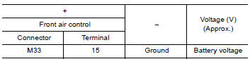
Is the inspection result normal?
YES >> Replace front air control. Refer to HAC "Removal and Installation".
NO >> Repair harness or connector between front air control and fuse.
 Blower fan on signal
Component Function Check 1.CHECK BLOWER FAN ON SIGNAL With CONSULT Turn ignition switch ON. Select "AIR CONDITIONER" of "BCM" using CONSULT. Select "FAN ON SIG" in "DATA MONITOR" mode, and ...
Front blower motor
Description The front blower motor utilizes a brush-less motor with a rotating magnet. Quietness is improved over previous motors where the brush was the point of contact and the coil rotated. ...
Other materials:
Meters and gauges
Type A (if so equipped)
1. Tachometer
2. Speedometer
3. Fuel gauge
4. Odometer
Twin trip odometer
Trip computer
5. Continuously Variable Transmission
(CVT) position indicator (if so equipped)
Automatic Transmission (A/T) position
indicator (if so equipped)
6. Instrument brightness con ...
Servicing air conditioner
The air conditioner system in your NISSAN vehicle
is charged with a refrigerant designed with
the environment in mind.
This refrigerant does not harm the earth's
ozone layer.
Special charging equipment and lubricant is required
when servicing your NISSAN air conditioner.
Using improper ...
Categories
- Manuals Home
- Nissan Versa Owners Manual
- Nissan Versa Service Manual
- Video Guides
- Questions & Answers
- External Resources
- Latest Updates
- Most Popular
- Sitemap
- Search the site
- Privacy Policy
- Contact Us

0.0057