Nissan Versa (N17): Blower fan on signal
Component Function Check
1.CHECK BLOWER FAN ON SIGNAL
With CONSULT
- Turn ignition switch ON.
- Select "AIR CONDITIONER" of "BCM" using CONSULT.
- Select "FAN ON SIG" in "DATA MONITOR" mode, and check status under the
following condition.
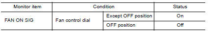
Is the inspection result normal?
YES >> Inspection End.
NO >> Refer to HAC "Diagnosis Procedure".
Diagnosis Procedure
Regarding Wiring Diagram information, refer to HAC "Wiring Diagram" or HAC "Wiring Diagram".
1.CHECK BLOWER FAN ON SIGNAL
- Turn ignition switch OFF.
- Disconnect front air control harness connector.
- Turn ignition switch ON.
- Check output waveform between front air control and ground with using
oscilloscope.
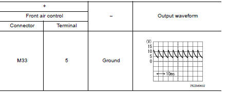
Is the inspection result normal?
YES >> Replace front air control. Refer to HAC "Removal and Installation".
NO >> GO TO 2.
2.CHECK BLOWER FAN ON SIGNAL CIRCUIT FOR OPEN
- Turn ignition switch OFF.
- Disconnect BCM connector.
- Check continuity front air control harness connector and BCM harness
connector.
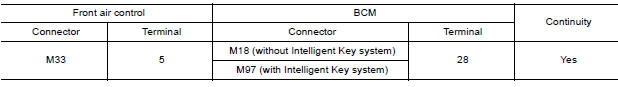
Is the inspection result normal?
YES >> GO TO 3.
NO >> Repair harness or connector.
3.CHECK BLOWER FAN ON SIGNAL CIRCUIT FOR SHORT
Check continuity between front air control harness connector and ground.
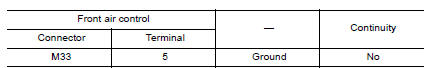
Is the inspection result normal?
YES >> Replace BCM. Refer to BCS "Removal and Installation" or BCS "Removal and Installation".
NO >> Repair harness or connector.
 A/C On signal
Component Function Check 1.CHECK A/C ON SIGNAL With CONSULT Turn ignition switch ON. Operate front blower motor. Select "AIR CONDITIONER" of "BCM" using CONSULT. Select "AIR COND SW" in ...
A/C Indicator
Diagnosis Procedure Regarding Wiring Diagram information, refer to HAC "Wiring Diagram" or HAC "Wiring Diagram". 1.CHECK A/C INDICATOR POWER SUPPLY Turn ignition switch O ...
Other materials:
Bluetooth Hands-Free Phone System without Navigation System (Type B) (if so
equipped)
WARNING
Use a phone after stopping your vehicle
in a safe location. If you have to use a
phone while driving, exercise extreme
caution at all times so full attention may
be given to vehicle operation.
If you are unable to devote full attention
to vehicle operation while talking on
...
Towing your vehicle
When towing your vehicle, all State (Provincial in
Canada) and local regulations for towing must be
followed. Incorrect towing equipment could damage
your vehicle. Towing instructions are available
from a NISSAN dealer. Local service operators
are generally familiar with the applicable laws
an ...
Categories
- Manuals Home
- Nissan Versa Owners Manual
- Nissan Versa Service Manual
- Video Guides
- Questions & Answers
- External Resources
- Latest Updates
- Most Popular
- Sitemap
- Search the site
- Privacy Policy
- Contact Us

0.0561