Nissan Versa (N17): A/C On signal
Component Function Check
1.CHECK A/C ON SIGNAL
With CONSULT
- Turn ignition switch ON.
- Operate front blower motor.
- Select "AIR CONDITIONER" of "BCM" using CONSULT.
- Select "AIR COND SW" in "DATA MONITOR" mode, and check status under the
following condition.
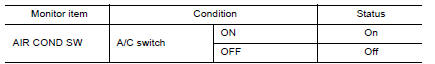
Is the inspection result normal?
YES >> Inspection End.
NO >> Refer to HAC "Diagnosis Procedure".
Diagnosis Procedure
Regarding Wiring Diagram information, refer to HAC "Wiring Diagram".
1.CHECK FUSE
- Turn ignition switch OFF.
- Check 10A fuse (No. 21, located in fuse block (J/B)].
NOTE: Refer to PG "Terminal Arrangement".
Is the inspection result normal?
YES >> GO TO 2.
NO >> Replace the blown fuse after repairing the affected circuit.
2.CHECK THERMO CONTROL AMP. POWER SUPPLY
- Turn ignition switch OFF.
- Disconnect thermo control amp. connector.
- Turn ignition switch ON.
- Check voltage between thermo control amp. harness connector and ground.
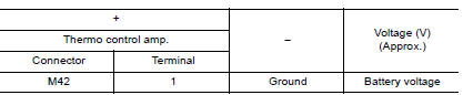
Is the inspection result normal?
YES >> GO TO 3.
NO >> Repair harness or connector between thermo control amp. and fuse.
3.CHECK THERMO CONTROL AMP. GROUND CIRCUIT FOR OPEN
- Turn ignition switch OFF.
- Check continuity between thermo control amp. harness connector and
ground
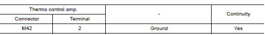
Is the inspection result normal?
YES >> GO TO 4.
NO >> Repair harness or connector.
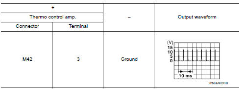
4.CHECK A/C ON SIGNAL
- Turn ignition switch ON.
- Check output waveform between thermo control amp. harness connector and
ground with using oscilloscope.
Is the inspection result normal?
YES >> GO TO 5.
NO >> GO TO 6.
5.CHECK FRONT AIR CONTROL
- Turn ignition switch OFF.
- Check front air control. Refer to HAC "Component Inspection".
Is the inspection result normal?
YES >> Replace thermo control amp. Refer to HAC "Removal and Installation".
NO >> Replace front air control. Refer to HAC "Removal and Installation".
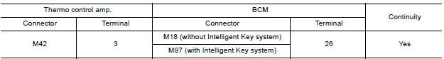
6.CHECK A/C ON SIGNAL CIRCUIT FOR OPEN
- Turn ignition switch OFF.
- Disconnect BCM and front air control connector.
- Check continuity between thermo control amp. harness connector and BCM
harness connector.
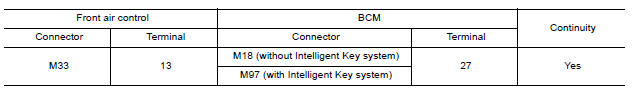
- Check continuity between front air control harness connector and BCM
harness connector.
Is the inspection result normal?
YES >> Replace BCM. Refer to BCS "Removal and Installation" or BCS "Removal and Installation".
NO >> Repair harness or connector.
Component Inspection
1.CHECK A/C CONTROL
Check continuity front air control terminals.
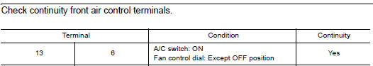
Is the inspection result normal?
YES >> Inspection End.
NO >> Replace front air control. Refer to HAC "Removal and Installation".
 Operation inspection
Work Procedure The purpose of the operation inspection is to check that the individual system operates normally. Check condition : Engine running at normal operating temperature. 1.CHECK F ...
Blower fan on signal
Component Function Check 1.CHECK BLOWER FAN ON SIGNAL With CONSULT Turn ignition switch ON. Select "AIR CONDITIONER" of "BCM" using CONSULT. Select "FAN ON SIG" in "DATA MONITOR" mode, and ...
Other materials:
Security systems (if so equipped)
Your vehicle has one type of security systems:
NISSAN Vehicle Immobilizer System
NISSAN vehicle immobilizer system
The NISSAN Vehicle Immobilizer System will not
allow the engine to start without the use of a
registered key.
If the engine fails to start using a registered key
(for ex ...
Starting the engine (models without NISSAN Intelligent Key system)
1. Apply the parking brake.
2. Automatic Transmission / CVT models:
Move the shift lever to P (Park) or N (Neutral).
P (Park) is recommended.
The shift lever cannot be moved out of
P (Park) and into any of the other gear
positions if the ignition key is turned to
the OFF position or if ...
Categories
- Manuals Home
- Nissan Versa Owners Manual
- Nissan Versa Service Manual
- Video Guides
- Questions & Answers
- External Resources
- Latest Updates
- Most Popular
- Sitemap
- Search the site
- Privacy Policy
- Contact Us

0.0048