Nissan Versa (N17): A/T Fluid
Inspection
FLUID LEAKAGE
- Check transaxle surrounding area (oil seal and plug etc.)for fluid leakage.
- If anything is found, repair or replace damaged parts and adjust A/ T fluid level. Refer to TM "Adjustment".
Changing
A/T fluid : Refer to TM "General Specification".
Fluid capacity : Refer to TM "General Specification".
CAUTION:
- Use only Genuine NISSAN Matic S ATF. Do not mix with other ATF.
- Using ATF other than Genuine NISSAN Matic S ATF will cause deterioration driveability and A/T durability, and may damagethe A/T, which is not covered by the warranty.
- Always use shop paper. Never use shop cloth.
- Replace a drain plug gasket with new ones at the final stage of the operation when installing.
- Use caution when looking into the drain hole as there is a risk of dripping fluid entering the eye.
- After replacement, always perform an ATF leakage check.
- Select "Data Monitor" in "TRANSMISSION" using CONSULT.
- Select "FLUID TEMP", and check that the A/T fluid temperature is 40 C (104F) or less.
- Check that the selector lever is in the "P" position, then completely engage the parking brake.
- Lift up the vehicle.
- Remove the drain plug and overflow tube, and then drain the ATF from the oil pan. Refer to TM "Removal and Installation".
- Install the charging pipe set (KV311039S0) (A) into the drain
hole.
CAUTION: Tighten the charging pipe by hand.
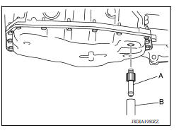
- Install the ATF changer hose (B) to the charging pipe.
CAUTION: Press the ATF changer hose all the way onto the charging pipe until it stops.
- Fill approximately 3 liters (2-5/8 lmp qt) of the ATF.
- Remove the ATF changer hose and charging pipe, then install
the drain plug.
NOTE: Perform this work quickly because ATF leaks.
- Lift down the vehicle.
- Start the engine.
- While depressing the brake pedal, shift the selector lever to the entire
position from "P" to "1", and shift it
to the "P" position.
NOTE: Hold the lever at each position for 5 seconds.
- Check that the CONSULT "Data Monitor" in "FLUID TEMP " is 35 to 45C (95 to 113F).
- Stop the engine.
- Lift up the vehicle.
- Remove the drain plug, and then drain the ATF from the oil pan.
- Repeat steps 6 to 16 (one time).
- Install the overflow tube. Refer to TM "Removal and Installation". CAUTION: Be sure to tighten to the specified torque. If it is not tightened to the specified torque, the tube may be damaged.
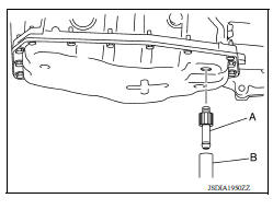
- Install the charging pipe set (KV311039S0) (A) into the drain
hole.
CAUTION: Tighten the charging pipe by hand.
- Install the ATF changer hose (B) to the charging pipe.
CAUTION: Press the ATF changer hose all the way onto the charging pipe until it stops.
- Fill approximately 3 liters (2-5/8 lmp qt) of the ATF.
- Remove the ATF changer hose and charging pipe, then install
the drain plug.
NOTE: Perform this work quickly because ATF leaks.
- Lift down the vehicle.
- Start the engine.
- While depressing the brake pedal, shift the selector lever to the entire
position from "P" to "1", and shift it
to the "P" position.
NOTE: Hold the lever at each position for 5 seconds.
- Check that the CONSULT "Data Monitor" in "FLUID TEMP " is 35 to 45C (95 to 113F).
- Lift up the vehicle.
- Remove the drain plug and check that ATF is drained out from the
overflow tube.
CAUTION: Perform this work with the vehicle idling.
NOTE: If the ATF is not drained out, refer to "Adjustment" and add ATF.
- When the flow of ATF slows to a drip, tighten the drain plug to the
specified torque. Refer to TM
"Removal and Installation".
CAUTION: Do not reuse drain plug gasket.
- Lift down the vehicle.
- Stop the engine.
Adjustment
A/T fluid : Refer to TM "General Specification".
Fluid capacity : Refer to TM "General Specification".
CAUTION:
- Use only Genuine NISSAN Matic S ATF. Never mix with other ATF.
- Using ATF other than Genuine NISSAN Matic S ATF will cause deterioration driveability and A/T durability, and may damagethe A/T, which is not covered by the warranty.
- During adjusting of the ATF level, check CONSULT so that the fluid temperature may be maintained from 35 to 45C (95 to 113F).
- Use caution when looking into the drain hole as there is a risk of dripping fluid entering the eye.
- Check that the selector lever is in the "P" position, then completely engage the parking brake.
- Start the engine.
- Adjust the ATF to be approximately 40C (104F).
NOTE: The ATF is largely affected by temperature. Therefore be sure to use CONSULT and check the "FLUID TEMP" under "TRANSMISSION" in "Data Monitor" while adjusting.
- While depressing the brake pedal, shift the selector lever to the entire
position from "P" to "1", and shift it
to the "P" position.
NOTE: Hold the lever at each position for 5 seconds.
- Lift up the vehicle.
- Check that there is no ATF leakage.
- Remove the drain plug. Refer to TM "Removal and Installation".
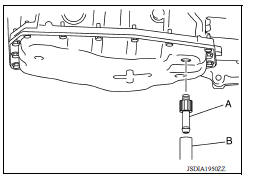
- Install the charging pipe set (KV311039S0) (A) into the drain
plug hole.
CAUTION: Tighten the charging pipe by hand.
- Install the ATF changer hose (B) to the charging pipe.
CAUTION: Press the ATF changer hose all the way onto the charging pipe until it stops.
- Fill approximately 0.5 liters (1/2 lmp qt) of the ATF.
-
Remove the ATF changer hose from the charging pipe, and check that the ATF drains out from the charging pipe. If it does not drain out, perform charging again.
CAUTION: Perform this work with the vehicle idling.
-
When the flow of ATF slows to a drip, disconnect the charging pipe from the oil pan.
-
Tighten the drain plug to the specified torque. Refer to TM "Removal and Installation".
CAUTION: Never reuse drain plug gasket.
-
Lift down the vehicle.
-
Stop the engine.
 Shift lock system
A/T Shift selector
Exploded View 1. Shift selector handle 2. Lock pin 3. Shift selector handle cover 4. Position indication panel 5. Shift selector assembly ...
Other materials:
P0733 3GR Incorrect ratio
Description
This malfunction is detected when the A/T does not shift into 3GR position as
instructed by TCM. This is not
only caused by electrical malfunction (circuits open or shorted) but by
mechanical malfunction such as control
valve sticking, improper solenoid valve operation, etc.
DTC ...
Wheel alignment
Inspection
DESCRIPTION
CAUTION:
The adjustment mechanisms of camber and toe-in are not included.
If camber and toe-in is outside the standard, check front
suspension parts for wear and damage.
Replace suspect parts if a malfunction is detected.
Measure wheel alignment under unladen ...
Categories
- Manuals Home
- Nissan Versa Owners Manual
- Nissan Versa Service Manual
- Video Guides
- Questions & Answers
- External Resources
- Latest Updates
- Most Popular
- Sitemap
- Search the site
- Privacy Policy
- Contact Us

0.0057