Nissan Versa (N17): Door lock function
DOOR LOCK FUNCTION : System Description
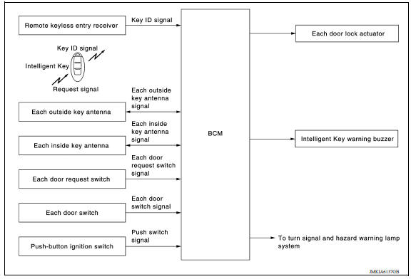
SYSTEM DIAGRAM
DOOR REQUEST SWITCH OPERATION
When pressing the request switch, it is possible to lock and unlock the door by carrying the Intelligent Key.
OPERATION DESCRIPTION
- When the BCM detects that each door request switch is pressed, it starts the outside key antenna and inside key antenna corresponding to the pressed door request switch and transmits the request signal to the Intelligent Key. And then, check that the Intelligent Key is near the door.
- If the Intelligent Key is within the outside key antenna detection area, it receives the request signal and transmits the key ID signal to the BCM via remote keyless entry receiver.
- BCM receives the key ID signal and compares it with the registered key ID.
- BCM transmits door lock/unlock signal and operates each door lock actuator. At the same time, BCM blinks hazard warning lamp (lock: 1 time, unlock: 2 times) and sounds Intelligent Key buzzer (lock: 1 time, unlock: 2 times) as a reminder.
OPERATION CONDITION
If the following conditions are satisfied, door lock/unlock operation is
performed if the door request switch is
operated.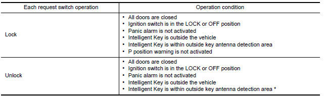
*: Even with a registered Intelligent Key remaining inside the vehicle, door locks can be unlocked from outside of the vehicle with a spare Intelligent Key as long as key IDs are different.
Door lock function can be changed using "LOCK/UNLOCK BY I-KEY" mode in "WORK SUPPORT". Refer to BCS "INTELLIGENT KEY : CONSULT Function (BCM - INTELLIGENT KEY)".
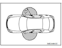
OUTSIDE KEY ANTENNA DETECTION AREA
The outside key antenna detection area of door lock/unlock function is in the range of approximately 80 cm (31.50 in) surrounding the driver, passenger door handles (1). However, this operating range depends on the ambient conditions.
HAZARD AND BUZZER REMINDER FUNCTION
For the operation check, BCM blinks hazard warning lamps (lock: 1 time, unlock: 2 times) and sounds Intelligent Key warning buzzer (lock: 1 time, unlock: 2 times) when door lock or unlock operates by operation of each door request switch.
How to Change Hazard and Buzzer Reminder Mode
Refer to BCS "INTELLIGENT KEY : CONSULT Function (BCM - INTELLIGENT KEY)".
AUTO DOOR LOCK FUNCTION
After door is unlocked by door request switch operation and if 30 seconds or
more passes without performing
the following operation, all doors are automatically locked. However, operation
check function does not activate.
Auto door lock mode can be changed by the "AUTO LOCK SET" mode in "WORK SUPPORT". Refer to BCS "INTELLIGENT KEY : CONSULT Function (BCM - INTELLIGENT KEY)".
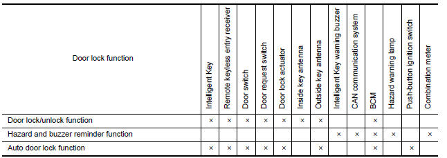
LIST OF OPERATION RELATED PARTS
Parts marked with × are the parts related to operation.
 Intelligent key system
INTELLIGENT KEY SYSTEM : System Description SYSTEM DIAGRAM SYSTEM DESCRIPTION The Intelligent Key system is a system that makes it possible to lock and unlock the door locks (door lock/ ...
Trunk open function
TRUNK OPEN FUNCTION : System Description System Diagram TRUNK LID OPENER OPERATION When the BCM detects that trunk lid opener switch is pressed, it starts the outside key antenna (rear ...
Other materials:
Intake valve timing control
Intake valve timing control : System Diagram
Intake valve timing control : system description
INPUT/OUTPUT SIGNAL CHART
Sensor
Input signal to ECM
ECM function
Actuator
Crankshaft position sensor (POS)
Engine speed*1
Piston position
Intake valve timing
con ...
Additional service when replacing
ECM
Description
When replacing ECM, the following procedure must be performed.
PROGRAMMING OPERATION
NOTE:
After replacing with a blank ECM, programming is required to write ECM
information. Be sure to follow the procedure
to perform the programming.
Work Procedure
1.CHECK ECM PART NUMBER
Che ...
Categories
- Manuals Home
- Nissan Versa Owners Manual
- Nissan Versa Service Manual
- Video Guides
- Questions & Answers
- External Resources
- Latest Updates
- Most Popular
- Sitemap
- Search the site
- Privacy Policy
- Contact Us

0.0056