Nissan Versa (N17): Intelligent key system
INTELLIGENT KEY SYSTEM : System Description
SYSTEM DIAGRAM
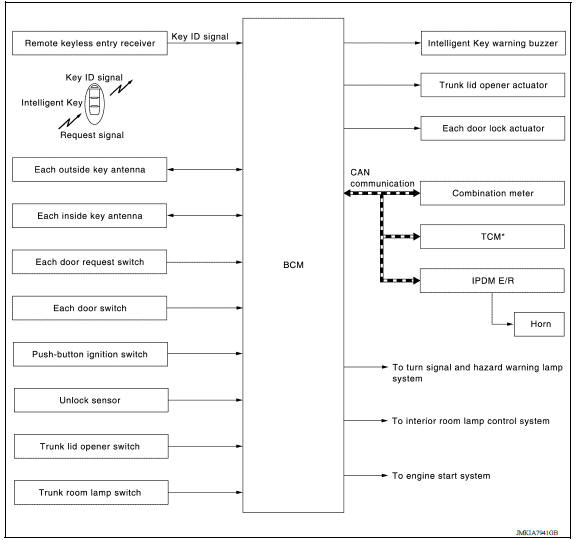
SYSTEM DESCRIPTION
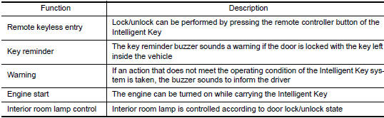
- The Intelligent Key system is a system that makes it possible to lock and unlock the door locks (door lock/ unlock function) by carrying the Intelligent Key, which operates based on the results of electronic ID verification using two-way communication between the Intelligent Key and the vehicle (BCM).
NOTE: The driver should always carry the Intelligent Key
- The settings for each function can be changed with CONSULT.
- If an Intelligent Key is lost, a new Intelligent Key can be registered. A maximum of 4 Intelligent Keys can be registered.
- It is possible to perform a diagnosis on the system and register an
Intelligent Key with CONSULT.
 System (power door lock system)
System Diagram System Description DOOR LOCK FUNCTION The door lock and unlock switch (driver side) is built into power window main switch. The door lock and unlock switch (pa ...
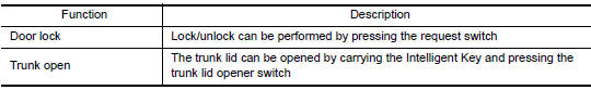
Door lock function
DOOR LOCK FUNCTION : System Description SYSTEM DIAGRAM DOOR REQUEST SWITCH OPERATION When pressing the request switch, it is possible to lock and unlock the door by carrying the Intelligent ...
Other materials:
Starting the engine (models without NISSAN Intelligent Key system)
1. Apply the parking brake.
2. Automatic Transmission / CVT models:
Move the shift lever to P (Park) or N (Neutral).
P (Park) is recommended.
The shift lever cannot be moved out of
P (Park) and into any of the other gear
positions if the ignition key is turned to
the OFF position or if ...
P0607 ECM
DTC Logic
DTC DETECTION LOGIC
DTC No.
Trouble diagnosis
(Trouble diagnosis content)
DTC detecting condition
Possible cause
P0607
ECM
(CAN communication bus)
When detecting error during the initial diagnosis
of CAN controller of ECM.
ECM
DTC CO ...
Categories
- Manuals Home
- Nissan Versa Owners Manual
- Nissan Versa Service Manual
- Video Guides
- Questions & Answers
- External Resources
- Latest Updates
- Most Popular
- Sitemap
- Search the site
- Privacy Policy
- Contact Us

0.0049