Nissan Versa (N17): ABS Branch line circuit
Diagnosis Procedure
1.CHECK CONNECTOR
1. Turn the ignition switch OFF.
2. Disconnect the battery cable from the negative terminal.
3. Check the terminals and connectors of the ABS actuator and electric unit (control unit) for damage, bend and loose connection (unit side and connector side).
Is the inspection result normal?
YES >> GO TO 2.
NO >> Repair the terminal and connector.
2.CHECK HARNESS FOR OPEN CIRCUIT
1. Disconnect the connector of ABS actuator and electric unit (control unit).
2. Check the resistance between the ABS actuator and electric unit (control
unit) harness connector terminals.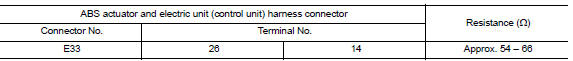
Is the measurement value within the specification?
YES >> GO TO 3.
NO >> Repair the ABS actuator and electric unit (control unit) branch line.
3.CHECK POWER SUPPLY AND GROUND CIRCUIT
Check the power supply and the ground circuit of the ABS actuator and electric unit (control unit). Refer to BRC "Diagnosis Procedure".
Is the inspection result normal?
YES (Present error)>>Replace the ABS actuator and electric unit (control unit). Refer to BRC "Removal and Installation".
YES (Past error)>>Error was detected in the ABS actuator and electric unit (control unit) branch line.
NO >> Repair the power supply and the ground circuit.
 ECM Branch line circuit
Diagnosis Procedure 1.CHECK CONNECTOR 1. Turn the ignition switch OFF. 2. Disconnect the battery cable from the negative terminal. 3. Check the terminals and connectors of the ECM for damage, be ...
IPDM-E Branch line circuit 
Diagnosis Procedure 1.CHECK CONNECTOR 1. Turn the ignition switch OFF. 2. Disconnect the battery cable from the negative terminal. 3. Check the terminals and connectors of the IPDM E/R for damage, ...
Other materials:
Wiper and washer switch
Switch operation
Type A (if so equipped)
The windshield wiper and washer operates when
the ignition switch is in the ON position.
Push the lever down to operate the wiper at the
following speed:
Intermittent (INT) - intermittent operation
can be adjusted by turning the knob toward
...
Uniform tire quality grading
DOT (Department of Transportation) Quality
Grades: All passenger car tires must conform to
federal safety requirements in addition to these
grades.
Quality grades can be found where applicable on
the tire sidewall between tread shoulder and
maximum section width. For example:
Treadwear 200 ...
Categories
- Manuals Home
- Nissan Versa Owners Manual
- Nissan Versa Service Manual
- Video Guides
- Questions & Answers
- External Resources
- Latest Updates
- Most Popular
- Sitemap
- Search the site
- Privacy Policy
- Contact Us

0.0102