Nissan Versa (N17): Drive belt
Exploded View
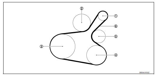
1. Generator 2. Water pump 3. Crankshaft pulley 4. A/C compressor (with A/C models) Idler pulley (without A/C models) 5. Idler pulley 6. Drive belt
Removal and Installation
REMOVAL
- Remove wheel and tire (RH) using power tool.
- Remove the fender protector (RH) front side clip.
- Loosen the lock nut (A), and then release the belt tension by turning the adjusting bolt (B).
- Remove the drive belt.
(1) : Generator
(2) : Water pump
(3) : Crankshaft pulley
(4) : A/C compressor (with A/C models): Idler pulley (without A/C models)
(5) : Idler pulley
(6) : Drive belt
INSTALLATION
1. Pull the idler pulley in the loosening direction, and then temporarily tighten the lock nut (A) to the following torque.
Lock nut (A) (Temporary tightening) : 4.4 N*m (0.45 kgm, 39 inlb)
(1) : Generator
(2) : Water pump
(3) : Crankshaft pulley
(4) : A/C compressor (with A/C models): Idler pulley (without A/C models)
(5) : Idler pulley
(6) : Drive belt
(B) : Adjusting bolt
NOTE:
Do not move the lock nut from the temporary tightened position. Go to step 2.
2. Install the drive belt on each pulley.
CAUTION:
- Check that there is no oil, grease, or coolant, etc. in pulley grooves.
- Check that the belt seats securely inside the groove on each pulley.
3. Adjust drive belt tension by turning the adjusting bolt.
CAUTION:
- Perform the belt tension adjustment with the lock nut temporarily tightened to the torque specification listed in step 1 which prevents the idler pulley from tilting.
- When checking immediately after installation, first adjust it to the specified value. Then, after turning crankshaft two turns or more, readjust to the specified value to avoid variation in deflection between pulleys.
4. Tighten the lock nut to final tightening specification.
Lock nut (Final tightening) : 34.8 N*m (3.5 kgm, 26 ftlb)
5. Check that belt tension is within the specification.
Inspection
- Inspection should be done only when engine is cold or over 30 minutes after the engine is stopped.
(1) : Generator
(2) : Water pump
(3) : Crankshaft pulley
(4) : A/C compressor (with A/C models): Idler pulley (without A/C models)
(5) : Idler pulley
(6) : Drive belt
- Visually check belt for wear, damage, and cracks on inside and edges.
- Turn crankshaft pulley clockwise twice, and check that the tension on all pulleys equalizes before testing.
- When measuring deflection, apply 98.1 N (10 kg, 22 lb) at the (
 ) marked point.
 - Measure the belt tension and frequency with acoustic tension gauge at
the (
 ) marked point.
CAUTION:
- When the tension and frequency are measured, the acoustic tension gauge should be used.
- When checking immediately after installation, first adjust it to the specified value. Then, after turning crankshaft two turns or more, readjust to the specified value to avoid variation in deflection between pulleys.
Adjustment
CAUTION:
- When belt is replaced with new one, adjust belt tension to the value for "New belt," because new belt will not fully seat in the pulley groove.
- When tension of the belt being used exceeds "Limit," adjust it to the value for "After adjusted."
- When installing a belt, check it is correctly engaged with the pulley groove.
- Do not allow oil or engine coolant to get on the belt.
- Do not twist or bend the belt strongly.
- Remove the fender protector (RH) front side clip.
- Tighten lock nut (A) temporarily to the following torque.
Lock nut (A)(Temporary tightening) : 4.4 N*m (0.45 kgm, 39 inlb)
(1) : Generator
(2) : Water pump
(3) : Crankshaft pulley
(4) : A/C compressor (with A/C models): Idler pulley (without A/C models)
(5) : Idler pulley
(6) : Drive belt
(B) : Adjusting bolt
- Adjust the belt tension by turning the adjusting bolt.
CAUTION:
- When checking immediately after installation, first adjust it to the specified value. Then, after turning crankshaft two turns or more, readjust to the specified value to avoid variation in deflection between pulleys.
- When the tension adjustment is performed, the lock nut should be in the condition at Step 2. If the tension adjustment is performed when the lock nut is loosened more than the temporary tightening, the idler pulley tilts and the correct tension adjustment cannot be performed.
- Tighten the lock nut to final tightening specification.
Lock nut (Final tightening) : 34.8 N*m (3.5 kgm, 26 ftlb)
 Noise, vibration and harshness (NVH) troubleshooting
NVH troubleshooting Chart Locate the area where noise occurs. Confirm the type of noise. Specify the operating condition of engine. Check specified noise source If necessary, repair ...
Air cleaner filter 
Exploded View 1. Clamp 2. PCV hose 3. Clamp 4. Mount rubber 5. Air duct (inlet) 6. Air cleaner body 7. Grommet 8. Air cleaner filter 9. Air cleaner cover 10. Mass air flow sensor 11. Air duct ...
Other materials:
Steering wheel
Tilt operation
Push the lock lever 1 down and adjust the
steering wheel up or down 2 to the desired
position.
Pull the lock lever 1 up to lock the steering
wheel in place.
WARNING
Do not adjust the steering wheel while
driving. You could lose control of your
vehicle and cause an accid ...
Clutch master cylinder
Exploded View
1. Reservoir hose 2. Master cylinder
Removal and Installation
CAUTION:
Do not spill clutch fluid onto painted surfaces. If fluid spills,
wipe up immediately and wash the
affected area with water.
Do not disassemble clutch master cylinder.
NOTE:
When removing compo ...
Categories
- Manuals Home
- Nissan Versa Owners Manual
- Nissan Versa Service Manual
- Video Guides
- Questions & Answers
- External Resources
- Latest Updates
- Most Popular
- Sitemap
- Search the site
- Privacy Policy
- Contact Us

0.0054