Nissan Versa (N17): Transaxle assembly
Exploded View
CASE AND HOUSING
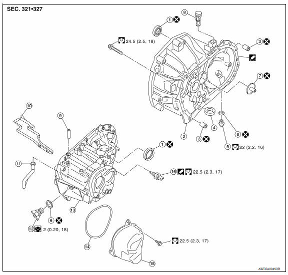
1. Differential side oil seal 2. Clutch housing 3. Dowel pin
4. Magnet 5. Drain plug 6. Gasket
7. Oil channel 8. Plug 9. 2-way connector
10. Oil gutter 11. Air breather inner tube 12. Filler plug
13. Transaxle case 14. O-ring 15. Rear housing
16. Position switch
 : Apply Genuine Silicone RTV or
equivalent. Refer to GI, "Recommended Chemical Products and Sealants".
: Apply Genuine Silicone RTV or
equivalent. Refer to GI, "Recommended Chemical Products and Sealants".
INPUT SHAFT AND GEAR
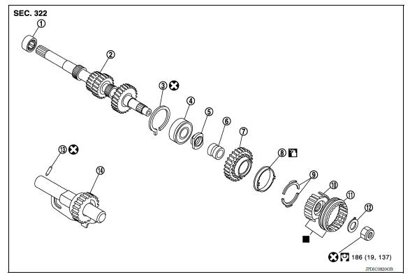
1. Input shaft front bearing 2. Input shaft 3. Snap ring 4. Input shaft rear bearing 5. Adapter plate 6. Bushing 7. 5th input gear 8. 5th-reverse baulk ring 9. Synchronizer lever 10. 5th-reverse synchronizer hub 11. 5th-reverse coupling sleeve 12. Lock washer 13. Retaining pin 14. Reverse gear
 : Apply gear oil.
 : Replace the parts as a set.
MAINSHAFT AND GEAR
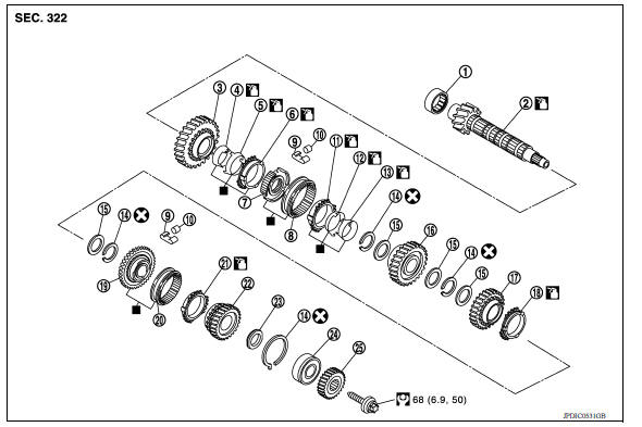
1. Mainshaft front bearing 2. Mainshaft 3. 1st main gear
4. 1st inner baulk ring 5. 1st synchronizer cone 6. 1st outer baulk ring
7. 1st-2nd synchronizer hub 8. 1st-2nd coupling sleeve 9. Spring
10. Insert key 11. 2nd outer baulk ring 12. 2nd synchronizer cone
13. 2nd inner baulk ring 14. Snap ring 15. Thrust washer
16. 2nd main gear 17. 3rd main gear 18. 3rd baulk ring
19. 3rd-4th synchronizer hub 20. 3rd-4th coupling sleeve 21. 4th baulk ring
22. 4th main gear 23. Spacer 24. Mainshaft rear bearing
25. 5th main gear
 : Apply gear oil.
 : Replace the parts as a set.
SHIFT FORK AND FORK ROD
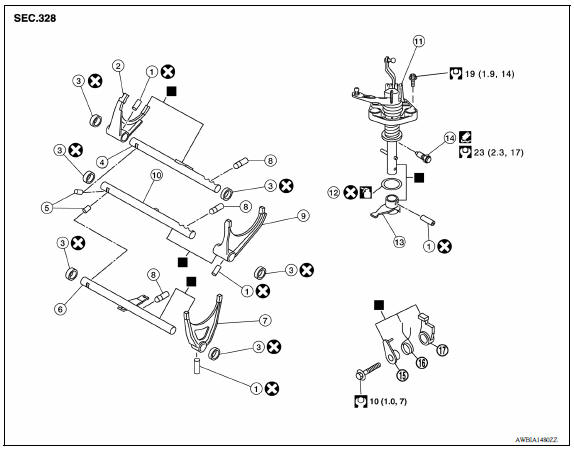
1. Retaining pin 2. 1st-2nd shift fork 3. Bushing
4. 1st-2nd fork rod 5. Lock pin 6. 5th-reverse fork rod
7. 5th-reverse shift fork 8. Check ball 9. 3rd-4th shift fork
10. 3rd-4th fork rod 11. Control shaft 12. O-ring
13. Selector 14. Check ball plug 15. Bushing
16. Spring 17. Gear catch
 : Apply gear oil.
 : Apply Genuine Silicone RTV or
equivalent. Refer to GI, "Recommended Chemical Products and Sealants".
: Apply Genuine Silicone RTV or
equivalent. Refer to GI, "Recommended Chemical Products and Sealants".
 : Replace the parts as a set.
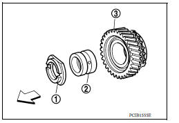
FINAL DRIVE
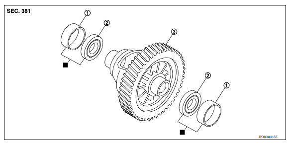
1. Differential side bearing outer race 2. Differential side bearing 3. Final
drive
 : Replace the parts as a set.
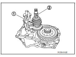
Disassembly
- Remove drain plug and gasket from clutch housing using suitable tool, and drain gear oil.
- Remove filler plug and gasket from transaxle case.
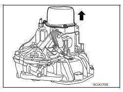
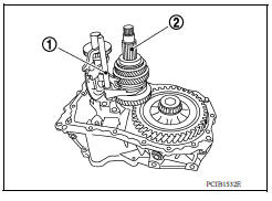
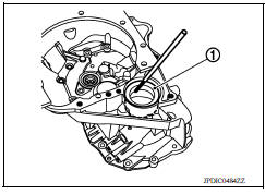
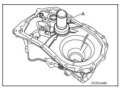
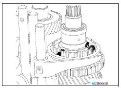
- Remove rear housing and O-ring.
CAUTION: Remove in direction of input shaft (
) as shown. Rear housing oil channel is inserted to input shaft center hole.
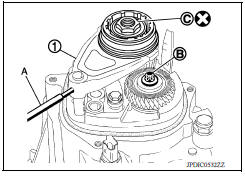
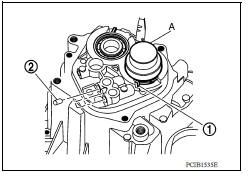
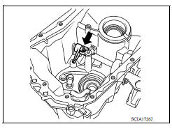
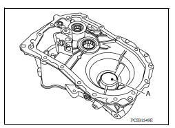
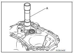
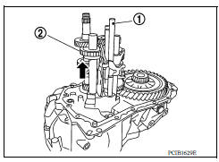
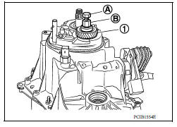
4. Move the shifter lever A (1) to the 3rd gear position.
NOTE:
- If it is not moved to the 3rd gear position, transaxle case cannot be removed from clutch housing.
- The 3rd gear position means that shifter lever A is fully rotated clockwise and it is returned approximately 10 degrees.
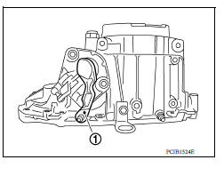
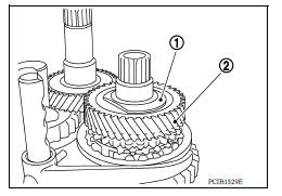
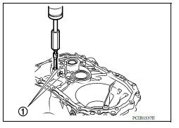
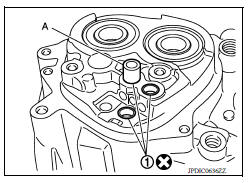
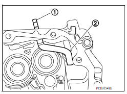
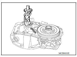
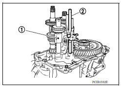
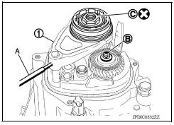
5. Remove 5th-reverse shift fork (1) and 5th-reverse coupling sleeve.
a. Remove retaining pin from 5th-reverse shift fork, using a suitable tool (A).
b. Press 5th-reverse shift fork, shift to 5th, and then engage it with 3rd gear.
c. Remove bolt (B).
d. Remove nut (C) and lock washer.
CAUTION:
- Do not reuse nut.
- Do not use an impact wrench for removal. Gears may be damaged.
e. Remove 5th-reverse shift fork and 5th-reverse coupling sleeve from 5th-reverse synchronizer hub.
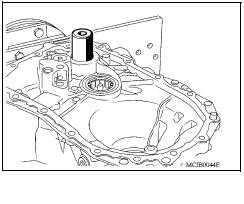
6. Remove 5th-reverse synchronizer hub from input shaft, using a suitable tool.
CAUTION: Set claw of suitable tool to the wider side of the hub when setting the suitable tool in 5th-reverse synchronizer hub.
7. Remove synchronizer levers, 5th-reverse baulk ring, 5th input gear, bushing, and adapter plate from input shaft.
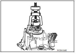
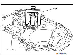
8. Remove 5th main gear from mainshaft, using Tools.
Tool number (A): KV32300QAC ( - )
(B): KV32300QAD ( - )
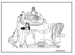
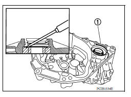
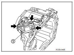
9. Remove position switch from transaxle case.
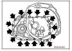
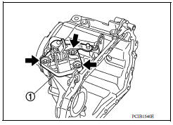
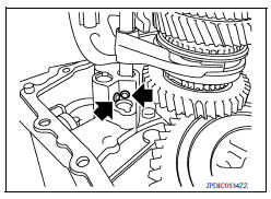
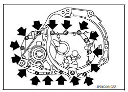
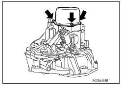
10. Remove transaxle case bolts (
).
11. Remove transaxle case from clutch housing.
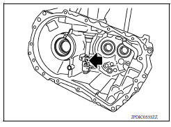
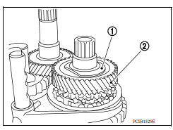
12. Remove spacer (1) and 4th main gear (2) from mainshaft.
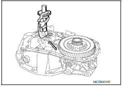
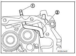
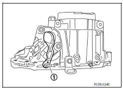
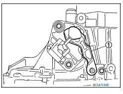
13. Remove 5th-reverse fork rod (1).
a. Pull 5th-reverse fork rod up until it contacts claw (
) of reverse gear (2).
b. Press gear portion of reverse gear down, and then remove 5threverse fork rod from clutch housing.
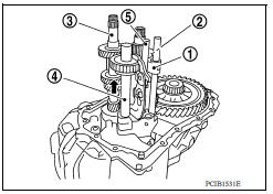
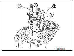
14. Remove 3rd-4th fork rod assembly (1), 3rd-4th coupling sleeve (2), and input shaft assembly (3).
a. Remove 4th baulk ring, insert keys, and springs from mainshaft.
b. Pull gear of reverse gear (4) up.
c. Pull 1st-2nd fork rod (5) up, and then maintain the neutral position.
d. Remove 3rd-4th fork rod assembly, 3rd-4th coupling sleeve, and input shaft assembly from clutch housing at the same time.
15. Remove retaining pin from 3rd-4th shift fork, using a pin punch.
16. Remove 3rd-4th shift fork from 3rd-4th shift fork rod.
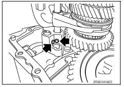
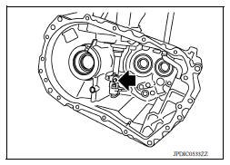
17. Remove lock pins (
) from clutch housing.
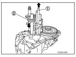
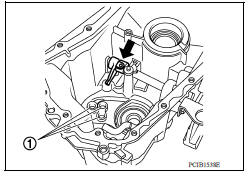
18. Remove 1st-2nd fork rod assembly (1) and mainshaft assembly (2) from clutch housing at the same time.
19. Remove retaining pin from 1st-2nd shift fork, using suitable tool.
20. Remove 1st-2nd shift fork from 1st-2nd shift fork rod.
21. Remove retaining pin from reverse gear, using suitable tool.
22. Remove reverse gear from clutch housing.
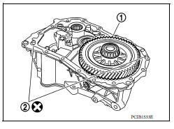
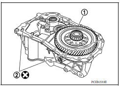
23. Remove final drive (1) from clutch housing.
24. Remove magnet and dowel pins (2) from clutch housing.
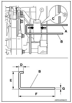
25. Remove plug (1) from clutch housing (2).
- (C): Plug
- (D): 15 mm (0.59 in)
- (E): 45 mm (1.77 in)
- (F): 95 mm (3.74 in) or more
- (G): 4 mm (0.16 in)
a. Install suitable tool (A) and (B) to the holes of clutch housing as shown.
b. While pressing the suitable tool (A) and (B) in the direction of the arrows shown, remove plug from clutch housing.
26. Remove input shaft front bearing from clutch housing, using suitable tool.
27. Cut oil channel tube at the base.
CAUTION: Do not reuse oil channel.
NOTE: Oil channel will be removed with the mainshaft front bearing.
28. Remove mainshaft front bearing and oil channel from clutch housing, using Tool (A).
Tool number : KV111011S0 ( - )
29. Remove bushings (1) from clutch housing, using suitable tool.
30. Remove differential side oil seals (1) from clutch housing and transaxle case, using suitable tool.
CAUTION: Do not damage transaxle case and clutch housing.
31. Remove differential side bearing outer races (1) from clutch housing and transaxle case, using suitable tool.
CAUTION: Do not damage transaxle case and clutch housing.
32. Pull 2-way connector (1) straight out to remove it from air breather inner tube (2).
33. Remove air breather inner tube from transaxle case.
34. Remove bushings (1) from transaxle case, using suitable tool.
35. Remove retaining pin (
) from selector, using suitable tool.
36. Remove selector from control shaft.
37. Remove oil gutter from transaxle case.
38. Remove bolt (
), and then remove bushing, spring, and gear catch from transaxle case.
39. Remove check ball plug from transaxle case.
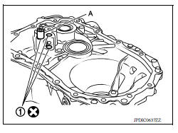
40. Remove bolts (
), and then remove control shaft (1) from transaxle case.
41. Remove O-ring from control shaft.
42. Expand snap rings (1) and remove input shaft rear bearing and mainshaft rear bearing from transaxle case, using Tool (A).
Tool number : ST35300000 ( - )
43. Remove snap rings from transaxle case.
44. Remove check balls (2) from transaxle case.
Assembly
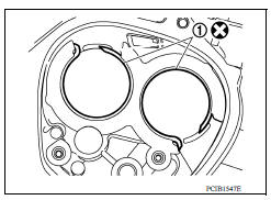
1. Install snap rings (1) along transaxle case groove so that notch mates with housing as shown.
CAUTION:
- Do not reuse snap rings.
- Check snap ring installation direction.
- Be sure to align notch with housing.
2. Expand snap rings (1) and install input shaft rear bearing and mainshaft rear bearing to transaxle case, using Tool (A).
CAUTION: Check that snap ring is correctly installed within bearing groove.
Tool number : ST35300000 ( - )
3. Install check balls (2) to transaxle case.
4. Install bushings (1) until they reach transaxle case, using suitable tool (A).
CAUTION: Do not reuse bushings.
5. Apply gear oil to O-ring, and then install it to control shaft.
CAUTION: Do not reuse O-ring.
6. Install control shaft (1) to transaxle case, and tighten bolts (
 )
to the specified torque.
)
to the specified torque.
CAUTION: Replace control shaft and selector as a set.
7. Install selector to control shaft, and then install retaining pin ( )
to selector, using suitable tool.
)
to selector, using suitable tool.
CAUTION:
- Be careful with the orientation of selector.
- Replace control shaft and selector as a set.
- Do not reuse retaining pin.
8. Install gear catch, spring, and bushing to transaxle case, and
then tighten bolt ( ) to the
specified torque.
) to the
specified torque.
CAUTION: Replace gear catch, spring, and bushing as a set.
9. Install oil gutter to transaxle case.
10. Install air breather inner tube (2) to transaxle case.
CAUTION: Do not damage air breather inner tube.
NOTE: It is easier to install when air breather inner tube end is wrapped and narrowed by tape. Remove tape after installation.
11. Insert 2-way connector (1) straight, and then install it to air breather inner tube.
CAUTION: Check air breather inner tube for twists after installing.
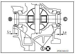
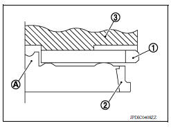
12. Install differential side oil seals (1) to clutch housing and transaxle case, using Tool.
(B) : Transaxle case side
(C) : Clutch housing side
Dimension (L1) : 5.7 - 6.3 mm (0.224 - 0.248 in)
Dimension (L2) : 2.4 - 3.0 mm (0.094 - 0.118 in)
Tool number : KV32500QAA ( - )
CAUTION:
- Do not reuse differential side oil seal.
- Do not tilt differential side oil seal.
- Do not damage clutch housing and transaxle case.
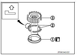
13. Install differential side bearing outer races until they reach clutch housing and transaxle case, using Tool (A).
CAUTION: Replace differential side bearing outer race and differential side bearing as a set.
Tool number : KV32300QAE ( - )
14. Install bushings (1) until they reach clutch housing, using suitable tool (A).
CAUTION: Do not reuse bushings.
15. Install oil channel to clutch housing.
CAUTION: Do not reuse oil channel.
16. Install mainshaft front bearing so that it becomes even with clutch housing surface, using Tool (A).
Tool number : ST33400001 ( - )
17. Install input shaft front bearing so that it becomes even with clutch housing surface, using Tool (A).
Tool number : KV40100900 ( - )
18. Install pinion gear, pinion shaft, and plug to clutch housing.
19. Install final drive (1) to clutch housing.
20. Install dowel pins (2) and magnet to clutch housing.
CAUTION: Do not reuse dowel pins.
21. Install reverse gear to clutch housing, and then install retaining pin to clutch housing, using suitable tool.
CAUTION: Do not reuse retaining pin.
22. Install 1st-2nd shift fork to 1st-2nd fork rod, and then install retaining pin to 1st-2nd shift fork.
CAUTION:
- Do not reuse retaining pin.
- Replace 1st-2nd fork rod and 1st-2nd shift fork as a set.
23. Set 1st-2nd fork rod assembly (1) onto mainshaft assembly (2), and then install them to clutch housing.
24. Install lock pins ( ) to
clutch housing.
) to
clutch housing.
25. Install 3rd-4th shift fork to 3rd-4th fork rod, and then install retaining pin to 3rd-4th shift fork.
CAUTION:
- Do not reuse retaining pin.
- Replace 3rd-4th fork rod and 3rd-4th shift fork as a set.
26. Install 3rd-4th fork rod assembly (1), 3rd-4th coupling sleeve (2), and input shaft assembly (3) to clutch housing.
a. Pull 1st-2nd fork rod (4) up, and then maintain the neutral position.
b. Set 3rd-4th fork rod assembly onto 3rd-4th coupling sleeve, and then install them together with input shaft assembly to clutch housing.
CAUTION:
- Set lock pin (3rd-4th fork rod side) onto 1st-2nd fork rod groove and then install 3rd-4th fork rod assembly.
- Be careful with the orientation of 3rd-4th coupling sleeve.
(A) : 4th main gear side
(B) : 3rd main gear side
- Install 3rd input gear of input shaft assembly so that it is set under reverse main gear of 3rd-4th coupling sleeve.
- Replace 3rd-4th coupling sleeve and 3rd-4th synchronizer hub as a set.
c. Install springs and insert keys to 3rd-4th synchronizer hub.
d. Apply gear oil to 4th baulk ring.
e. Install 4th baulk ring.
27. Install 5th-reverse fork rod (1) to clutch housing.
CAUTION: Replace 5th-reverse fork rod and 5th-reverse shift fork as a set.
a. Pull gear of reverse gear (2) up.
b. Temporarily install 5th-reverse fork rod to clutch housing.
c. Press gear of reverse gear (1) down and then install 5th-reverse fork rod (2) to clutch housing.
CAUTION:
Set levers of 5th-reverse fork rod so as to align with reverse
gear groove ( ).
).
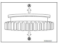
28. Install 4th main gear (2) and spacer (1) to mainshaft.
CAUTION: Install spacer so that spacer protrusion faces rear side of transaxle.
29. Press 3rd-4th shift fork down and then shift 3rd-4th coupling sleeve to 3rd gear side.
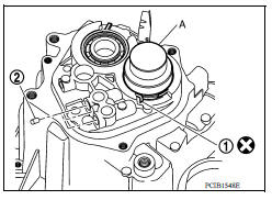
30. Move the shifter lever A (1) to the 3rd gear position.
NOTE:
- If it is not moved to the 3rd gear position, transaxle case cannot be installed to clutch housing.
- The 3rd gear position means that shifter lever A is fully rotated clockwise and it is returned approximately 10 degrees.
31. Apply recommended sealant to transaxle case mating surface of clutch housing.
CAUTION:
- Use Genuine Silicone RTV or equivalent. Refer to GI, "Recommended Chemical Products and Sealants".
- Do not allow old Silicone RTV, moisture, oil, or foreign matter to remain on mating surface.
- Check that mating surface is not damaged.
- Apply a continuous bead of Silicone RTV to the mating surface.
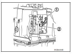
32. Install transaxle case to clutch housing. If it is difficult to install, slightly rotate shifter lever A counterclockwise, and then install.
(1) : Selector
(2) : Shift fork
CAUTION:
- Do not damage Silicone RTV bead with transaxle case or other objects during installation.
- Be careful to align the lever of 5th-reverse fork rod with reverse gear groove.
33. Rotate input shaft so that bearing and shaft fit each other, and
then tighten transaxle bolts (  ) to
the specified torque.
) to
the specified torque.
34. Apply recommended sealant to position switch thread and check ball plug thread. Install to transaxle case and tighten to specified torque.
CAUTION:
- Use Genuine Silicone RTV or equivalent. Refer to GI, "Recommended Chemical Products and Sealants".
- Do not allow old Silicone RTV, moisture, oil, or foreign matter to remain on thread.
35. Apply gear oil to mainshaft spline.
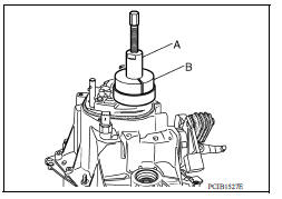
36. Install 5th main gear (1) to mainshaft, using a suitable bolt (A) [M10 x 1.0] and a suitable nut (B).
37. Install adapter plate (1), bushing (2), and 5th input gear (3) to input shaft.
CAUTION: Be careful with the orientation of adapter plate.
 : Transaxle case side
38. Install 5th-reverse synchronizer hub, 5th-reverse coupling sleeve, and 5th-reverse shift fork.
a. Apply gear oil to 5th-reverse baulk ring.
b. Install 5th-reverse baulk ring (1) to 5th input gear.
: 5th-reverse synchronizer hub
side
CAUTION: Be careful with the orientation of 5th-reverse baulk ring.
c. Install synchronizer levers (2) to 5th-reverse synchronizer hub (3).
CAUTION:
- Replace 5th-reverse synchronizer hub and 5th-reverse coupling sleeve as a set.
- Be careful with the orientation of synchronizer lever.
d. Install 5th-reverse synchronizer hub assembly and lock washer to input shaft.
CAUTION:
- Be careful with the orientation of 5th-reverse synchronizer hub.
: 5th input gear side
- Do not allow synchronizer lever (1) to overlap 5th-reverse baulk ring protrusion (A).
(2) : 5th-reverse baulk ring
(3) : 5th-reverse synchronizer hub
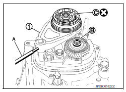
e. Set 5th-reverse shift fork (1) to 5th-reverse coupling sleeve, and then install them to 5th-reverse fork rod and input shaft.
CAUTION: Do not reuse nut.
(A) : Suitable tool
(B) : Bolt
(C) : Nut
CAUTION:
- Be careful with the orientation of 5th-reverse coupling sleeve.
 : 5th input gear side
- Replace 5th-reverse synchronizer hub and 5th-reverse coupling sleeve as a set.
- Replace 5th-reverse shift fork and 5th-reverse fork rod as a set.
f. Check that the shifter lever A is in the 3rd position. Press 5threverse shift fork (1) and move shifter lever A to 5th gear.
(A) : Suitable tool
g. Tighten bolt (B) to the specified torque.
h. Tighten nut (C) to the specified torque.
CAUTION: Do not reuse nut.
i. Install retaining pin to 5th-reverse shift fork, using suitable tool.
CAUTION: Do not reuse retaining pin.
39. Move shifter lever A (1) to the neutral position.
40. Install O-ring to rear housing.
CAUTION: Do not reuse O-ring.
41. Install rear housing to transaxle case, and tighten bolts (
 ) to
the specified torque.
) to
the specified torque.
CAUTION:
- Do not reuse O-ring.
- Do not pinch O-ring when installing rear housing.
42. Install drain plug.
a. Install gasket to drain plug.
CAUTION: Do not reuse gasket.
b. Install drain plug to clutch housing, using suitable tool.
c. Tighten drain plug to the specified torque.
43. Install filler plug.
a. Install gasket to filler plug, and then install filler plug to transaxle case.
CAUTION: Do not reuse gasket.
b. Tighten filler plug to the specified torque.
CAUTION: Fill with gear oil before tightening filler plug to the specified torque.
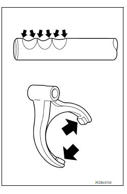
Inspection
INSPECTION AFTER DISASSEMBLY
Check contact surface and sliding surface of fork rod and shift fork for excessive wear, uneven wear, and damage. Replace if necessary.
 Transaxle assembly
Exploded View 1. Transaxle assembly : Refer to "INSTALLATION" in TM, "Removal and Installation" for the locations and tightening torque. ...
Input shaft and gear
Exploded View 1. Input shaft front bearing 2. Input shaft 3. Snap ring 4. Input shaft rear bearing 5. Adapter plate 6. Bushing 7. 5th input gear 8. 5th-reverse baulk ring 9. Synchronizer lever ...
Other materials:
Final drive
Exploded View
1. Differential side bearing outer race 2. Differential side bearing 3. Final
drive
: Replace the parts as a set.
Disassembly
Remove differential side bearings, using Tool (A) and suitable tool.
Tool number : ST33052000 ( - )
Assembly
Install differential sid ...
P0711 Transmission fluid temperature
sensor A
DTC Logic
DTC DETECTION LOGIC
DTC
Trouble diagnosis name
DTC detection condition
Possible causes
P0711
Transmission Fluid Temperature
Sensor "A" Circuit Range/
Performance
Under the following diagnosis
conditions, A/T fluid temperature
does not rise to ...
Categories
- Manuals Home
- Nissan Versa Owners Manual
- Nissan Versa Service Manual
- Video Guides
- Questions & Answers
- External Resources
- Latest Updates
- Most Popular
- Sitemap
- Search the site
- Privacy Policy
- Contact Us

0.0062