Nissan Versa (N17): Power supply and ground circuit
Audio unit
AUDIO UNIT : Diagnosis Procedure
Regarding Wiring Diagram information, refer to AV"Wiring Diagram".
1.CHECK FUSE
Check that the following fuses are not blown.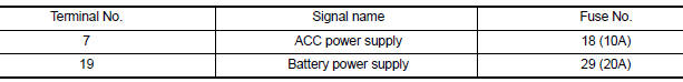
Are the fuses blown?
YES >> Replace the blown fuse after repairing the affected circuit.
NO >> GO TO 2.
2.CHECK POWER SUPPLY CIRCUIT
1. Turn ignition switch OFF.
2. Disconnect audio unit connector M44.
3. Check voltage between audio unit connector M44 and ground.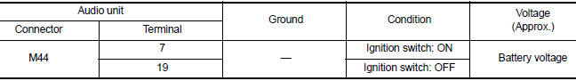
Is the inspection result normal?
YES >> GO TO 3.
NO >> Repair or replace harness or connectors.
3.CHECK GROUND CIRCUIT
1. Turn ignition switch OFF.
2. Disconnect audio unit connector M45.
3. Check continuity between audio unit connector M45 and ground.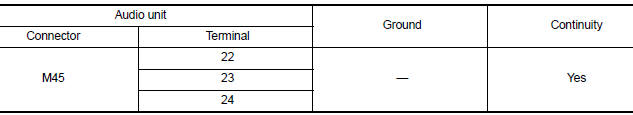
Is the inspection result normal?
YES >> Inspection End.
NO >> Repair or replace harness or connectors.
Bluetooth control unit
BLUETOOTH CONTROL UNIT : Diagnosis Procedure
Regarding Wiring Diagram information, refer to AV "Wiring Diagram".
1.CHECK FUSE
Check that the following fuses are not blown.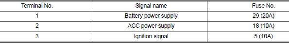
Are the fuses blown?
YES >> Replace the blown fuse after repairing the affected circuit.
NO >> GO TO 2.
2.CHECK POWER SUPPLY CIRCUIT
1. Turn ignition switch OFF.
2. Disconnect Bluetooth control unit connector B33.
3. Check voltage between Bluetooth control unit connector B33 and ground.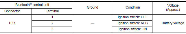
Is the inspection result normal?
YES >> GO TO 3.
NO >> Repair or replace harness or connectors.
3.CHECK GROUND CIRCUIT
1. Turn ignition switch OFF.
2. Check continuity between Bluetooth control unit connector B33 and ground.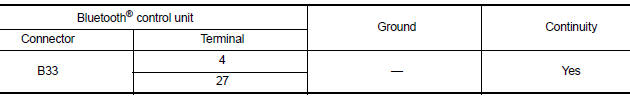
Is the inspection result normal?
YES >> Inspection End.
NO >> Repair or replace harness or connectors.
 Diagnosis and repair workflow
Work Flow OVERALL SEQUENCE DETAILED FLOW 1.GET INFORMATION FOR SYMPTOM Get detailed information from the customer about the symptom (the condition and the environment when the incident/malf ...
Front door speaker
Diagnosis Procedure Regarding Wiring Diagram information, refer to AV "Wiring Diagram". 1.CONNECTOR CHECK Check the audio unit and speaker connectors for the following: Proper conne ...
Other materials:
Battery
Keep the battery surface clean and dry.
Clean the battery with a solution of baking
soda and water.
Make certain the terminal connections are
clean and securely tightened.
If the vehicle is not to be used for 30 days or
longer, disconnect the negative (-) battery
terminal cable to ...
Recommended fluids/lubricants and capacities
The following are approximate capacities. The actual refill capacities may
be a little different. When refilling, follow the procedure
described in the "Do-it-yourself" section to determine the proper refill
capacity.
...
Categories
- Manuals Home
- Nissan Versa Owners Manual
- Nissan Versa Service Manual
- Video Guides
- Questions & Answers
- External Resources
- Latest Updates
- Most Popular
- Sitemap
- Search the site
- Privacy Policy
- Contact Us

0.0056