Nissan Versa (N17): Front door speaker
Diagnosis Procedure
Regarding Wiring Diagram information, refer to AV "Wiring Diagram".
1.CONNECTOR CHECK
Check the audio unit and speaker connectors for the following:
- Proper connection
- Damage
- Disconnected or loose terminals
Is the inspection result normal?
YES >> GO TO 2
NO >> Repair the terminals or connectors.
2.CHECK FRONT DOOR SPEAKER SIGNAL CIRCUIT CONTINUITY
1. Disconnect audio unit connector M44 and suspect front door speaker connector.
2. Check continuity between audio unit connector M44 and suspect front door
speaker connector.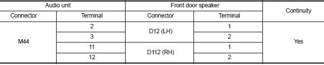
3. Check continuity between audio unit connector M44 and ground.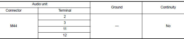
Is the inspection result normal?
YES >> GO TO 3
NO >> Repair or replace harness or connectors.
3.CHECK FRONT DOOR SPEAKER SIGNAL
1. Connect audio unit connector M44 and suspect front door speaker connector.
2. Turn ignition switch to ACC.
3. Push audio unit POWER switch.
4. Check signal between the terminals of audio unit connector M44.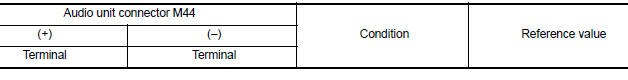
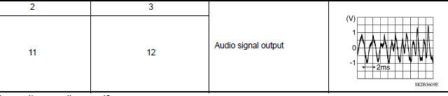
Is the inspection result normal?
YES >> Replace front door speaker. Refer to AV "Removal and Installation".
NO >> Replace audio unit. Refer to AV "Removal and Installation".
 Power supply and ground circuit
Rear door speaker
Diagnosis Procedure Regarding Wiring Diagram information, refer to AV "Wiring Diagram". 1.CONNECTOR CHECK Check the audio unit and speaker connectors for the following: Proper conne ...
Other materials:
Rear oil seal
REAR OIL SEAL : Removal and Installation
REMOVAL
Remove transaxle assembly.
Remove clutch cover and clutch disk (M/T models).
Remove flywheel (M/T models) or drive plate (A/T or CVT models).
Remove rear oil seal with a suitable tool.
CAUTION:
Be careful not to damage crankshaft an ...
P074B Unable to engage 3GR
Description
This malfunction is detected when the A/T does not shift into 3GR position as
instructed by TCM. This is not
only caused by electrical malfunction (circuits open or shorted) but by
mechanical malfunction such as control
valve sticking, improper solenoid valve operation, etc.
DTC ...
Categories
- Manuals Home
- Nissan Versa Owners Manual
- Nissan Versa Service Manual
- Video Guides
- Questions & Answers
- External Resources
- Latest Updates
- Most Popular
- Sitemap
- Search the site
- Privacy Policy
- Contact Us

0.0048