
Nissan Versa (N17): Rear door speaker
Diagnosis Procedure
Regarding Wiring Diagram information, refer to AV "Wiring Diagram".
1.CONNECTOR CHECK
Check the audio unit and speaker connectors for the following:
- Proper connection
- Damage
- Disconnected or loose terminals
Is the inspection result normal?
YES >> GO TO 2
NO >> Repair the terminals or connectors.
2.CHECK REAR DOOR SPEAKER SIGNAL CIRCUIT CONTINUITY
1. Disconnect audio unit connector M44 and suspect rear door speaker connector.
2. Check continuity between audio unit connector M44 and suspect rear door
speaker connector.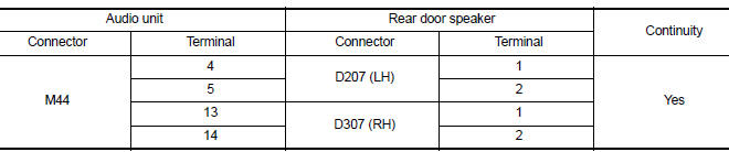
3. Check continuity between audio unit connector M44 and ground.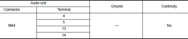
Is the inspection result normal?
YES >> GO TO 3
NO >> Repair or replace harness or connectors.
3.CHECK REAR DOOR SPEAKER SIGNAL
1. Connect audio unit connector M44 and suspect rear door speaker connector.
2. Turn ignition switch to ACC.
3. Push audio unit POWER switch.
4. Check signal between the terminals of audio unit connector M44.
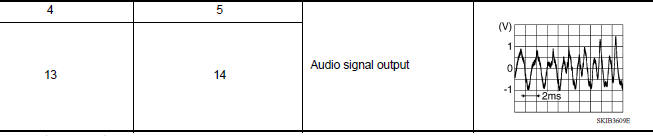
Is the inspection result normal?
YES >> Replace rear door speaker. Refer to AV "Removal and Installation".
NO >> Replace audio unit. Refer to AV "Removal and Installation".
 Front door speaker
Diagnosis Procedure Regarding Wiring Diagram information, refer to AV "Wiring Diagram". 1.CONNECTOR CHECK Check the audio unit and speaker connectors for the following: Proper conne ...
Bluetooth voice signal circuit
Diagnosis Procedure Regarding Wiring Diagram information, refer to AV "Wiring Diagram". 1.CHECK BLUETOOTH VOICE SIGNAL CIRCUIT CONTINUITY 1. Turn ignition switch OFF. 2. Disconnect audio ...
Other materials:
Hazard warning flasher switch
Push the switch on to warn other drivers when
you must stop or park under emergency conditions.
All turn signal lights flash.
WARNING
If stopping for an emergency, be sure to
move the vehicle well off the road.
Do not use the hazard warning flashers
while moving on the highway unl ...
Ignition timing
Inspection
1.CHECK IGNITION TIMING
1. Attach timing light (A) to loop wire (1) as
shown.
2. Check ignition timing.
1 : Timing indicator
>> INSPECTION END
...
Categories
- Manuals Home
- Nissan Versa Owners Manual
- Nissan Versa Service Manual
- Video Guides
- Questions & Answers
- External Resources
- Latest Updates
- Most Popular
- Sitemap
- Search the site
- Privacy Policy
- Contact Us

0.0057