Nissan Versa (N17): B2198 NATS antenna AMP
DTC Logic
DTC DETECTION LOGIC 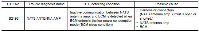
DTC CONFIRMATION PROCEDURE
1.PERFORM DTC CONFIRMATION PROCEDURE
1. Make the conditions that BCM enters in the low power consumption mode (BCM sleep condition).
Refer to BCS "BODY CONTROL SYSTEM : System Description".
2. Turn ignition switch ON.
3. Check DTC in Self Diagnostic Result mode of BCM using CONSULT.
Is DTC detected?
YES >> Go to SEC "Diagnosis Procedure".
NO >> Inspection End.
Diagnosis Procedure
Regarding Wiring Diagram information, refer to SEC "Wiring Diagram".
1.CHECK FUSE
1. Turn power switch OFF.
2. Check that the following fuse in IPDM E/R is not blown. 
Is the inspection result normal?
YES >> GO TO 2.
NO >> Replace the blown fuse after repairing the cause of blowing.
2.CHECK NATS ANTENNA AMP. POWER SUPPLY
1. Disconnect NATS antenna amp. connector.
2. Check voltage between NATS antenna amp. harness connector and ground. 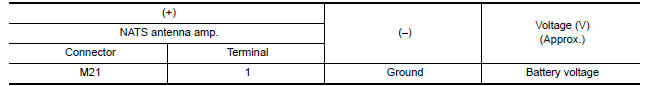
Is the inspection result normal?
YES >> GO TO 4.
NO >> GO TO 3.
3.CHECK NATS ANTENNA AMP. POWER SUPPLY CIRCUIT
1. Disconnect IPDM E/R connector.
2. Check continuity between IPDM E/R harness connector and NATS antenna amp.
connector.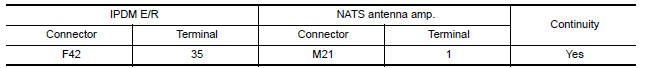
Is the inspection result normal?
YES >> Replace IPDM E/R. Refer to PCS "Removal and Installation".
NO >> Repair or replace harness.
4.CHECK NATS ANTENNA AMP. GROUND CIRCUIT
Check continuity between NATS antenna amp. harness connector and ground. 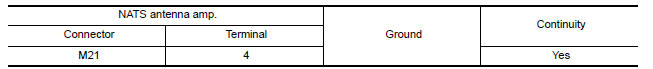
Is the inspection result normal?
YES >> GO TO 5.
NO >> Repair or replace harness.
5.CHECK NATS ANTENNA AMP. COMMUNICATION SIGNAL 1
Check voltage signal between NATS antenna amp. harness connector and ground
using an oscilloscope.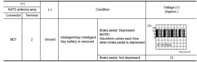
Is the inspection result normal?
YES >> GO TO 7.
NO >> GO TO 6.
6.CHECK NATS ANTENNA AMP. OUTPUT SIGNAL CIRCUIT 1
1. Disconnect BCM connector.
2. Check continuity between NATS antenna amp. harness connector and BCM
connector. 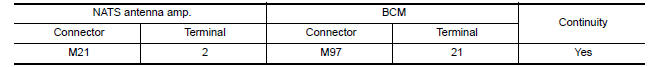
3. Check continuity between NATS antenna amp. harness connector and ground.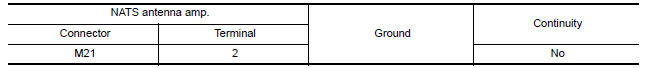
Is the inspection result normal?
YES >> GO TO 9.
NO >> Repair or replace harness.
7.CHECK NATS ANTENNA AMP. COMMUNICATION SIGNAL 2
Check voltage signal between NATS antenna amp. harness connector and ground
using an oscilloscope. 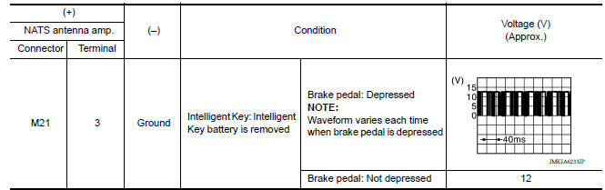
Is the inspection result normal?
YES >> Replace NATS antenna amp. Refer to SEC "Removal and Installation".
NO >> GO TO 8.
8.CHECK NATS ANTENNA AMP. OUTPUT SIGNAL CIRCUIT 2
1. Disconnect BCM connector.
2. Check continuity between NATS antenna amp. harness connector and BCM
connector.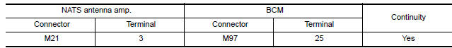
3. Check continuity between NATS antenna amp. harness connector and ground. 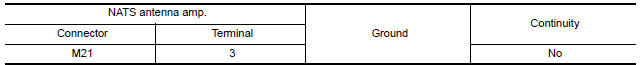
Is the inspection result normal?
YES >> GO TO 9.
NO >> Repair or replace harness.
9.REPLACE BCM
1. Replace BCM. Refer to BCS "Removal and Installation".
2. Perform initialization of BCM and registration of all Intelligent Keys using CONSULT.
>> Inspection End
 B2196 Dongle unit
Description BCM performs ID verification between BCM and dongle unit. When verification result is OK, BCM permits cranking. ...

Other materials:
Readiness for inspection/maintenance (I/M) test
Due to legal requirements in some states and
Canadian Provinces, your vehicle may be required
to be in what is called the "ready condition"
for an Inspection/Maintenance (I/M) test of
the emission control system.
The vehicle is set to the "ready condition" when it
is driven through certain d ...
Consult function
APPLICATION ITEMS
Diagnostic test mode
Function
Work Support
This mode enables a technician to adjust some devices faster and
more accurately.
Self Diagnostic Results
Retrieve DTC from ECU and display diagnostic items.
Data Monitor
Monitor the input ...
Categories
- Manuals Home
- Nissan Versa Owners Manual
- Nissan Versa Service Manual
- Video Guides
- Questions & Answers
- External Resources
- Latest Updates
- Most Popular
- Sitemap
- Search the site
- Privacy Policy
- Contact Us

0.0058