Nissan Versa (N17): B2555 Stop lamp
DTC Logic
DTC DETECTION LOGIC 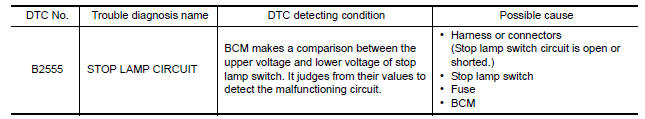
DTC CONFIRMATION PROCEDURE
1.PERFORM DTC CONFIRMATION PROCEDURE
1. Depress brake pedal and wait 1 second or more.
2. Check DTC in Self Diagnostic Result mode of BCM using CONSULT.
Is DTC detected?
YES >> Go to SEC Diagnosis Procedure.
NO >> Inspection End.
Diagnosis Procedure
Regarding Wiring Diagram information, refer to SEC "Wiring Diagram".
1.CHECK STOP LAMP SWITCH INPUT SIGNAL 1
1. Turn ignition switch OFF.
2. Disconnect BCM connector.
3. Check voltage between BCM harness connector and ground. 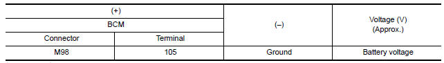
Is the inspection normal?
YES >> GO TO 2.
NO-1 >> Check 10 A fuse [No. 30, located in the fuse block (J/B)].
NO-2 >> Check harness for open or short between BCM and fuse.
2.CHECK STOP LAMP SWITCH POWER SUPPLY CIRCUIT
1. Disconnect stop lamp switch connector.
2. Check voltage between stop lamp switch harness connector and ground. 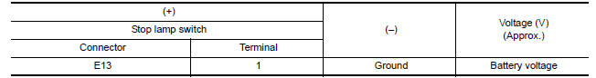
Is the inspection result normal?
YES >> GO TO 3.
NO >> Check harness for open or short between stop lamp switch and fuse.
3.CHECK STOP LAMP SWITCH INPUT SIGNAL 2
1. Connect stop lamp switch connector.
2. Check voltage between BCM harness connector and ground. 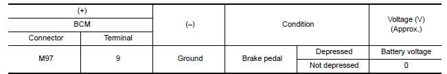
Is the inspecting result normal?
YES >> GO TO 4.
NO >> GO TO 5.
4.REPLACE BCM
1. Replace BCM. Refer to BCS "Removal and Installation".
2. Perform initialization of BCM and registration of all Intelligent Keys using CONSULT.
>> Inspection End.
5.CHECK STOP LAMP SWITCH CIRCUIT
1. Disconnect stop lamp switch connector.
2. Check continuity between stop lamp switch harness connector and BCM
harness connector. 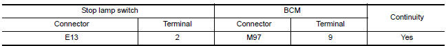
3. Check continuity between stop lamp switch harness connector and ground. 
Is the inspection result normal?
YES >> GO TO 6.
NO >> Repair or replace harness.
6.CHECK STOP LAMP SWITCH
Refer to SEC "Component Inspection".
Is the inspection result normal?
YES >> GO TO 7.
NO >> Replace stop lamp switch. Refer to BR "Exploded View".
7.CHECK INTERMITTENT INCIDENT
Refer to GI "Intermittent Incident".
>> Inspection End.
Component Inspection
1.CHECK STOP LAMP SWITCH
1. Turn ignition switch OFF.
2. Disconnect stop lamp switch connector.
3. Check continuity between stop lamp switch terminals. 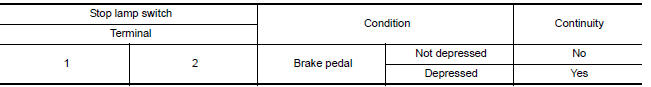
Is the inspection result normal?
YES >> Inspection End.
NO >> Replace stop lamp switch. Refer to BR "Exploded View".
 B2198 NATS antenna AMP
Other materials:
Engine compartment check locations
HR16DE Engine
1. Drive belt location
2. Engine oil filler cap
3. Air cleaner
4. Brake and clutch (if so equipped) fluid
reservoir
5. Fusible link
6. Battery
7. Engine coolant reservoir
8. Radiator cap
9. Engine oil dipstick
10. Windshield-washer fluid reservoir
Refer to the page numb ...
Rear parcel shelf finisher
Exploded View
1. High-mounted stop lamp 2. Rear parcel shelf finisher 3. Seat belt finisher
4. Seatback latch cover 5. Top tether strap anchor 6. Top tether strap anchor
finisher
Front
Pawl
Removal and Installation
REMOVAL
Remove high-mounted stop lamp. Refer to EXL "Removal ...
Categories
- Manuals Home
- Nissan Versa Owners Manual
- Nissan Versa Service Manual
- Video Guides
- Questions & Answers
- External Resources
- Latest Updates
- Most Popular
- Sitemap
- Search the site
- Privacy Policy
- Contact Us

0.0061