Nissan Versa (N17): B2626 Outside antenna
DTC Logic
DTC DETECTION LOGIC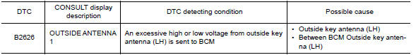
DTC CONFIRMATION PROCEDURE
1.PERFORM DTC CONFIRMATION PROCEDURE
- Turn ignition switch ON.
- Check "Self Diagnostic Result" mode of "BCM" using CONSULT.
Is DTC detected?
YES >> Refer to DLK "Diagnosis Procedure".
NO >> Outside key antenna (LH) is OK.
Diagnosis Procedure
Regarding Wiring Diagram information, refer to DLK "INTELLIGENT KEY SYSTEM : Wiring Diagram".
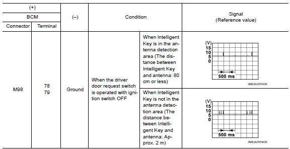
1.CHECK OUTSIDE KEY ANTENNA INPUT SIGNAL 1
- Turn ignition switch ON.
- Check signal between BCM harness connector and ground using
oscilloscope.
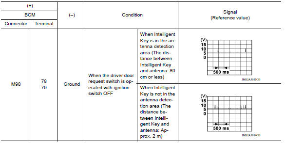
Is the inspection result normal?
YES >> Replace BCM. Refer to BCS "Removal and Installation".
NO >> GO TO 2.
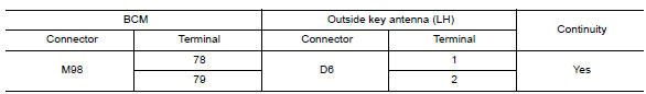
2.CHECK OUTSIDE KEY ANTENNA CIRCUIT
- Turn ignition switch OFF.
- Disconnect BCM connector and outside key antenna (LH) connector.
- Check continuity between BCM harness connector and outside key antenna (LH)
harness connector.
- Check continuity between BCM harness connector and ground.
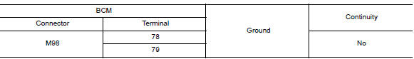
Is the inspection result normal?
YES >> GO TO 3.
NO >> Repair or replace harness.
3.CHECK OUTSIDE KEY ANTENNA INPUT SIGNAL 2
- Replace outside key antenna (LH). (New antenna or other antenna)
- Connect BCM connector and outside key antenna (LH) connector.
- Turn ignition switch ON.
- Check signal between BCM harness connector and ground using
oscilloscope.
Is the inspection result normal?
YES >> Replace outside key antenna (LH).
NO >> Replace BCM. Refer to BCS "Removal and Installation".
 B2623 Inside antenna
Other materials:
Reporting safety defects
For USA
If you believe that your vehicle has a defect
which could cause a crash or could
cause injury or death, you should immediately
inform the National Highway Traffic
Safety Administration (NHTSA) in addition
to notifying NISSAN.
If NHTSA receives similar complaints, it
may open an inv ...
U0300 Can communication data
Description
The amount of data transmitted from each control unit is read.
DTC Logic
DTC DETECTION LOGIC
DTC
Trouble diagnosis name
DTC detection condition
Possible causes
U0300
Internal Control Module Software
Incompatibility
When the amount of data transmitt ...
Categories
- Manuals Home
- Nissan Versa Owners Manual
- Nissan Versa Service Manual
- Video Guides
- Questions & Answers
- External Resources
- Latest Updates
- Most Popular
- Sitemap
- Search the site
- Privacy Policy
- Contact Us

0.0104