Nissan Versa (N17): B2627 Outside antenna
DTC Logic
DTC DETECTION LOGIC 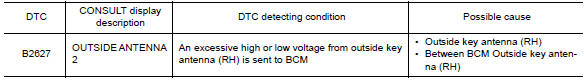
DTC CONFIRMATION PROCEDURE
1.PERFORM DTC CONFIRMATION PROCEDURE
- Turn ignition switch ON.
- Check Self Diagnostic Result mode of BCM using CONSULT.
Is outside key antenna DTC detected?
YES >> Refer to DLK "Diagnosis Procedure".
NO >> Outside key antenna (RH) is OK.
Diagnosis Procedure
Regarding Wiring Diagram information, refer to DLK"INTELLIGENT KEY SYSTEM : Wiring Diagram".
1.CHECK OUTSIDE KEY ANTENNA INPUT SIGNAL 1
- Turn ignition switch ON.
- Check signal between BCM harness connector and ground using
oscilloscope.
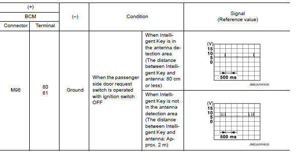
Is the inspection result normal?
YES >> Replace BCM. Refer to BCS "Removal and Installation".
NO >> GO TO 2.
2.CHECK OUTSIDE KEY ANTENNA CIRCUIT
- Turn ignition switch OFF.
- Disconnect BCM connector and outside key antenna (RH) connector.
- Check continuity between BCM harness connector and outside key antenna (RH)
harness connector.

- Check continuity between BCM harness connector and ground.
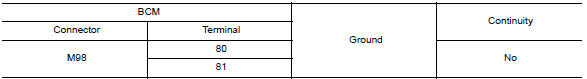
Is the inspection result normal?
YES >> GO TO 3.
NO >> Repair or replace harness.
3.CHECK OUTSIDE KEY ANTENNA INPUT SIGNAL 2
- Replace outside key antenna (RH). (New antenna or other antenna)
- Connect BCM connector and outside key antenna (RH) connector.
- Turn ignition switch ON.
- Check signal between BCM harness connector and ground using
oscilloscope.
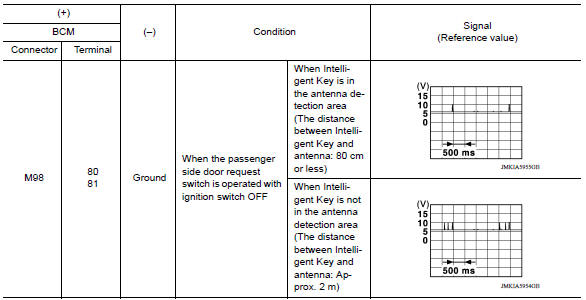
Is the inspection result normal?
YES >> Replace outside key antenna (RH).
NO >> Replace BCM. Refer to BCS "Removal and Installation".
 B2626 Outside antenna
Other materials:
Control panel buttons - color screen with Navigation System (if so equipped)
WARNING
Positioning of the heating or air conditioning
controls and display controls
should not be done while driving in order
that full attention may be given to
the driving operation.
Do not disassemble or modify this system.
If you do, it may result in accidents,
fire, or elec ...
Main line between IPDM-E and DLC
circuit
Diagnosis Procedure
1.CHECK CONNECTOR
1. Turn the ignition switch OFF.
2. Disconnect the battery cable from the negative terminal.
3. Check the following terminals and connectors for damage, bend and loose
connection (connector side
and harness side).
Harness connector E7
Harness connec ...
Categories
- Manuals Home
- Nissan Versa Owners Manual
- Nissan Versa Service Manual
- Video Guides
- Questions & Answers
- External Resources
- Latest Updates
- Most Popular
- Sitemap
- Search the site
- Privacy Policy
- Contact Us

0.0066