Nissan Versa (N17): Battery
Removal and Installation
REMOVAL
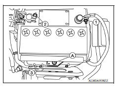
1. Disconnect the battery negative terminal (1).
CAUTION: When disconnecting, disconnect the battery negative terminal first.
2. Disconnect the battery positive terminal (2).
3. Remove the battery wedge bolt (A) and battery wedge bracket (3).
4. Remove the battery cover.
5. Remove the battery.
INSTALLATION
Installation is in the reverse order of removal.
CAUTION:
- When connecting, connect the battery positive terminal first.
- Check battery terminals for poor connection caused by corrosion.
Battery wedge bracket bolt : 17.0 N*m (1.7 kg-m, 13 ft-lb)
Battery terminal nuts : 5.4 N*m (0.55 kg-m, 48 in-lb)
Reset electronic systems as necessary. Refer to PG "ADDITIONAL SERVICE WHEN REMOVING BATTERY NEGATIVE TERMINAL : Special Repair Requirement".
SERVICE DATA AND SPECIFICATIONS (SDS)
Battery
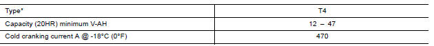
*: Always check with the Parts Department for the latest parts information.
 Harness connector
Description HARNESS CONNECTOR (TAB-LOCKING TYPE) The tab-locking type connectors help prevent accidental looseness or disconnection. The tab-locking type connectors are disconnected by pushi ...
Meter, warning lamp & indicator (MWI)
TYPE A HOW TO USE THIS MANUAL APPLICATION NOTICE Information ...
Other materials:
P1715 Input speed sensor
Description
ECM receives input speed sensor signal from TCM via the CAN communication
line. ECM uses this signal for
engine control.
DTC Logic
DTC DETECTION LOGIC
NOTE:
If DTC P1715 is displayed with DTC UXXXX, first perform the
trouble diagnosis for DTC UXXXX.
If DTC P1715 is displa ...
Control linkage
Exploded View
1. Shifter lever A 2. Selector lever 3. Selector cable
4. Shifter cable 5. Cable mounting bracket 6. Tapping bolt
7. Bracket 8. Grommet 9. M/T shift selector assembly
10. Shift selector 11. Shift selector handle
Removal and Installation
REMOVAL
Move the shift selector to ...
Categories
- Manuals Home
- Nissan Versa Owners Manual
- Nissan Versa Service Manual
- Video Guides
- Questions & Answers
- External Resources
- Latest Updates
- Most Popular
- Sitemap
- Search the site
- Privacy Policy
- Contact Us

0.0052