Nissan Versa (N17): Harness connector
Description
HARNESS CONNECTOR (TAB-LOCKING TYPE)
- The tab-locking type connectors help prevent accidental looseness or disconnection.
- The tab-locking type connectors are disconnected by pushing or lifting the locking tab(s). Refer to the figure below.
Refer to the next page for description of the slide-locking type connector.
CAUTION: Do not pull the harness or wires when disconnecting the connector.
[Example]
![[Example]](images/books/322/85/index571.gif)
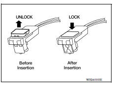
HARNESS CONNECTOR (SLIDE-LOCKING TYPE)
- A new style slide-locking type connector is used on certain systems and components, especially those related to OBD.
- The slide-locking type connectors help prevent incomplete locking and accidental looseness or disconnection.
- The slide-locking type connectors are disconnected by pushing or pulling the slider. Refer to the figure below.
CAUTION:
- Do not pull the harness or wires when disconnecting the connector.
- Be careful not to damage the connector support bracket when disconnecting the connector.
[Example]
![[Example]](images/books/322/85/index572.jpg)
HARNESS CONNECTOR (LEVER LOCKING TYPE)
- Lever locking type harness connectors are used on certain control units and control modules such as ECM, ABS actuator and electric unit (control unit), etc.
- Lever locking type harness connectors are also used on super multiple junction (SMJ) connectors.
- Always confirm the lever is fully locked in place by moving the lever as far as it will go to ensure full connection.
CAUTION: Always confirm the lever is fully released (loosened) before attempting to disconnect or connect these connectors to avoid damage to the connector housing or terminals.
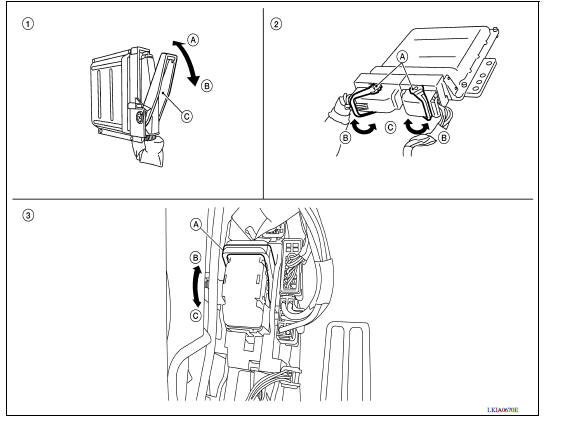
1. Control unit with single lever 2. Control unit with dual lever 3. SMJ connector A. Fasten A. Lever A. Lever B. Loosen B. Fasten B. Fasten C. Lever C. Loosen C. Loosen
HARNESS CONNECTOR (DIRECT-CONNECT SRS COMPONENT TYPE)
- SRS direct-connect type harness connectors are used on certain SRS components such as air bag modules and seat belt pre-tensioners.
- Always pull up to release black locking tab prior to removing connector from SRS components.
- Always push down to lock black locking tab after installing connector to SRS components.When locked, the black locking tab is level with the connector housing.
CAUTION: Do not pull the harness or wires when removing connectors from SRS components.
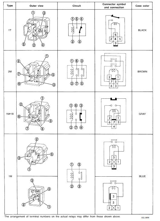
STANDARDIZED RELAY
Description
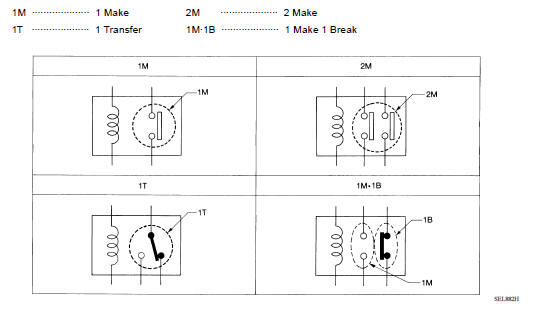
NORMAL OPEN, NORMAL CLOSED AND MIXED TYPE RELAYS
Relays can mainly be divided into three types: normal open, normal closed and mixed type relays.
TYPE OF STANDARDIZED RELAYS
FUSE BLOCK - JUNCTION BOX (J/B)
Terminal Arrangement
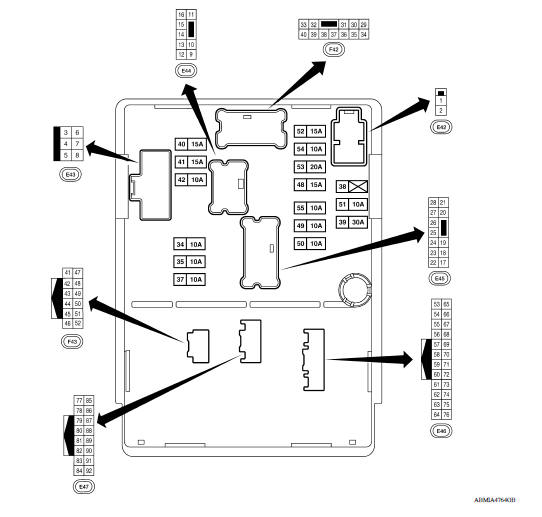
FUSE, FUSIBLE LINK AND RELAY BOX
Terminal Arrangement
FUSE AND FUSIBLE LINK BOX
IPDM E/R (INTELLIGENT POWER DISTRIBUTION MODULE ENGINE ROOM)
IPDM E/R Terminal Arrangement
REMOVAL AND INSTALLATION
 Harness
Harness Layout HOW TO READ HARNESS LAYOUT The following Harness Layouts use a map style grid to help locate connectors on the drawings: Main Harness Engine Room Harness Engine Room Harnes ...
Battery
Removal and Installation REMOVAL 1. Disconnect the battery negative terminal (1). CAUTION: When disconnecting, disconnect the battery negative terminal first. 2. Disconnect the battery positive ...
Other materials:
U1001 CAN comm circuit
Description
CAN (Controller Area Network) is a serial communication line for real time
application. It is an onvehicle multiplex
communication line with high data communication speed and excellent error
detection ability. Many electronic
control units are equipped onto a vehicle, and each con ...
Front drive shaft
Exploded View
1. Drive shaft 2. Cotter pin A. Apply Molykote M77
Removal and Installation
REMOVAL
Remove the wheel and tire assembly using power tool. Refer to WT
"Adjustment".
Remove wheel sensor and sensor harness. Refer to BRC "FRONT WHEEL SENSOR
: Removal and
...
Categories
- Manuals Home
- Nissan Versa Owners Manual
- Nissan Versa Service Manual
- Video Guides
- Questions & Answers
- External Resources
- Latest Updates
- Most Popular
- Sitemap
- Search the site
- Privacy Policy
- Contact Us

0.0048