Nissan Versa (N17): Harness
Harness Layout
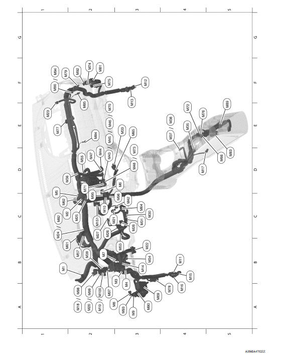
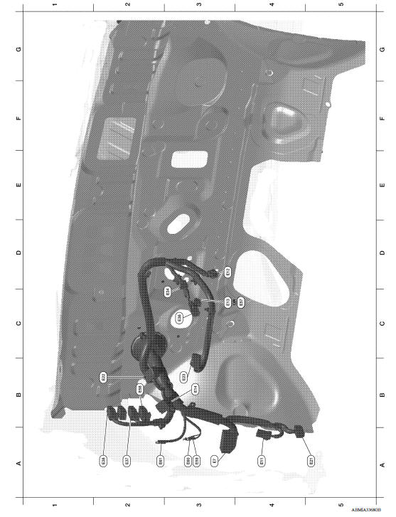
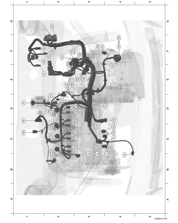
HOW TO READ HARNESS LAYOUT
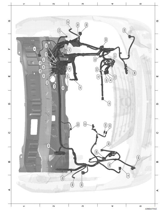
The following Harness Layouts use a map style grid to help locate connectors on the drawings:
- Main Harness
- Engine Room Harness
- Engine Room Harness (Passenger Compartment)
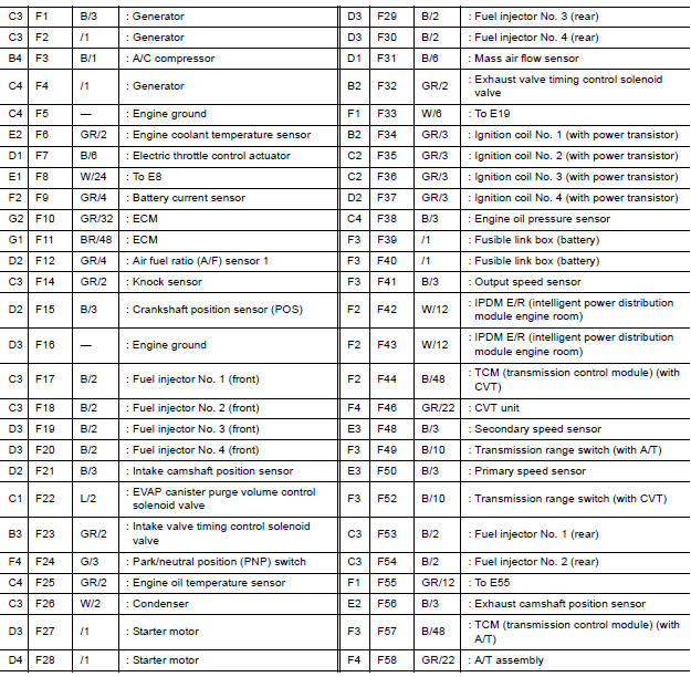
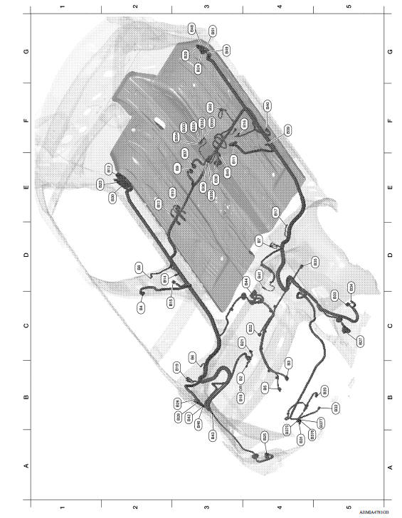
- Engine Control Harness
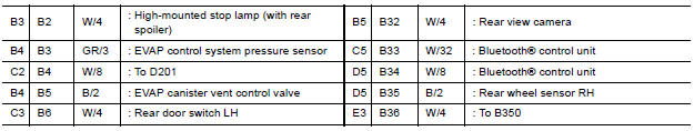
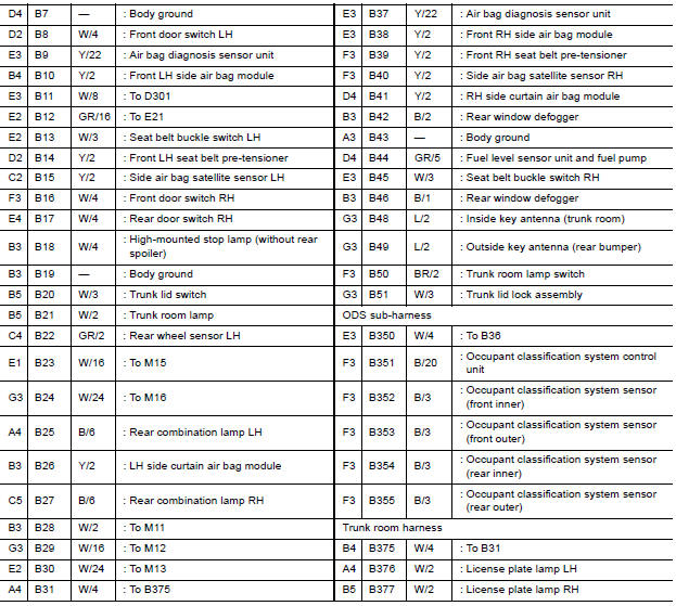
- Body Harness, Trunk Room Harness and ODS Sub-harness
- Room Lamp Harness
To use the grid reference
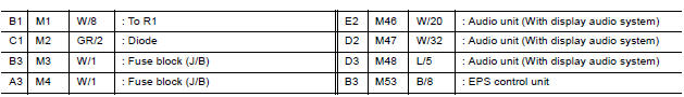
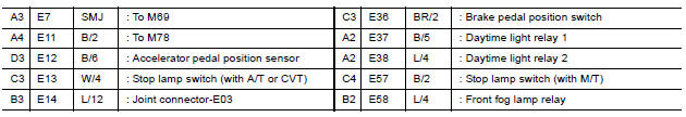
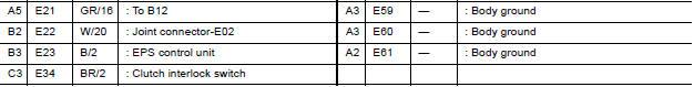
1. Find the desired connector number on the connector list.
2. Find the grid reference.
3. On the drawing, find the crossing of the grid reference letter column and number row.
4. Find the connector number in the crossing zone.
5. Follow the line (if used) to the connector.
OUTLINE
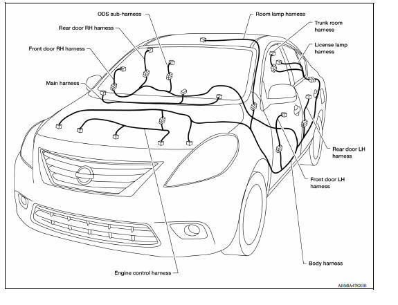
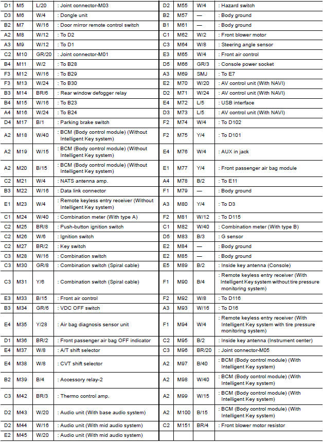
MAIN HARNESS
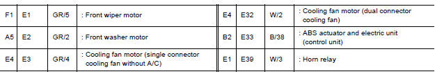
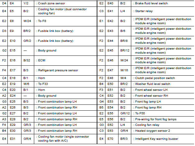
ENGINE ROOM HARNESS
ENGINE ROOM HARNESS (PASSENGER COMPARTMENT)
ENGINE CONTROL HARNESS
BODY HARNESS
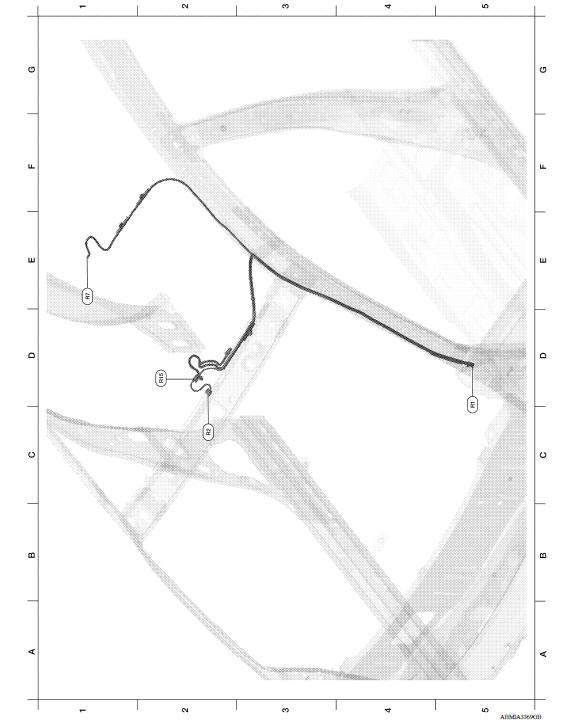
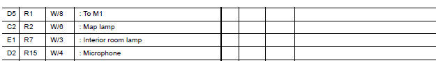
ROOM LAMP HARNESS
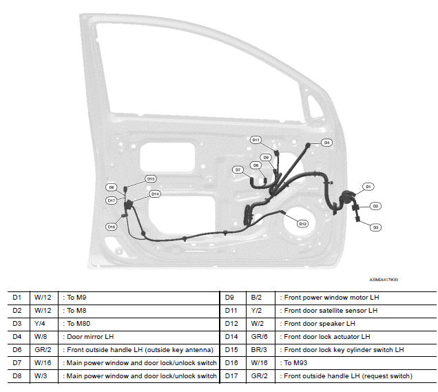
FRONT DOOR LH HARNESS
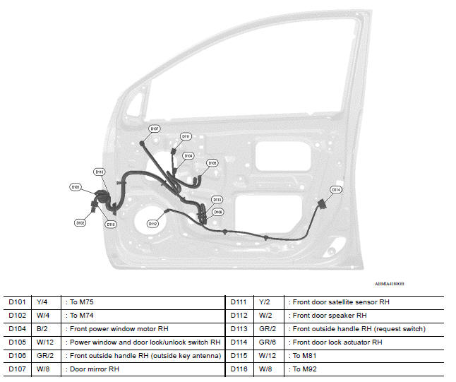
FRONT DOOR RH HARNESS
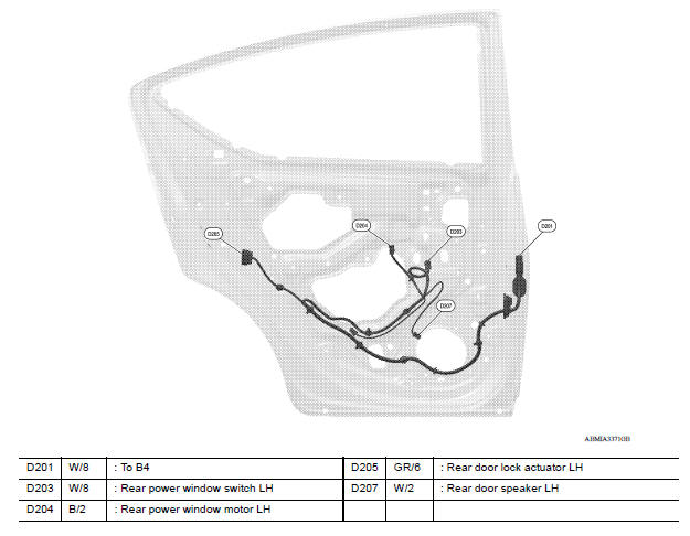
REAR DOOR LH HARNESS
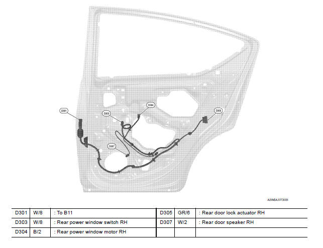
REAR DOOR RH HARNESS
ELECTRICAL UNITS LOCATION
Electrical Units Location
ENGINE COMPARTMENT
PASSENGER COMPARTMENT
LUGGAGE COMPARTMENT
 Power supply routing circuit
Wiring Diagram - Battery Power Supply - Wiring Diagram - Accessory Power Supply - Wiring Diagram - Ignition Power Supply - ...
Harness connector
Description HARNESS CONNECTOR (TAB-LOCKING TYPE) The tab-locking type connectors help prevent accidental looseness or disconnection. The tab-locking type connectors are disconnected by pushi ...
Other materials:
Noise, vibration and harshness (NVH) troubleshooting
NVH troubleshooting Chart
Locate the area where noise occurs.
Confirm the type of noise.
Specify the operating condition of engine.
Check specified noise source
If necessary, repair or replace these parts.
Location
of noise
Type of
noise
Operating condition of
...
Control cable
Exploded View
1. Bracket B 2. Lock plate 3. Transaxle assembly
4. Bracket A 5. Control cable 6. CVT shift selector assembly
A: Manual lever B: Grommet
Removal and Installation
CAUTION:
Always apply the parking brake before performing removal and installation.
REMOVAL
Remove the batt ...
Categories
- Manuals Home
- Nissan Versa Owners Manual
- Nissan Versa Service Manual
- Video Guides
- Questions & Answers
- External Resources
- Latest Updates
- Most Popular
- Sitemap
- Search the site
- Privacy Policy
- Contact Us

0.0053