Nissan Versa (N17): BCM
Reference Value
NOTE: The Signal Tech II Tool (J-50190) can be used to perform the following functions. Refer to the Signal Tech II User Guide for additional information.
- Activate and display TPMS transmitter IDs
- Display tire pressure reported by the TPMS transmitter
- Read TPMS DTCs
- Register TPMS transmitter IDs
- Check Intelligent Key relative signal strength
- Confirm vehicle Intelligent Key antenna signal strength
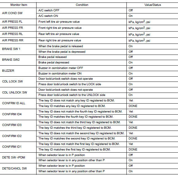
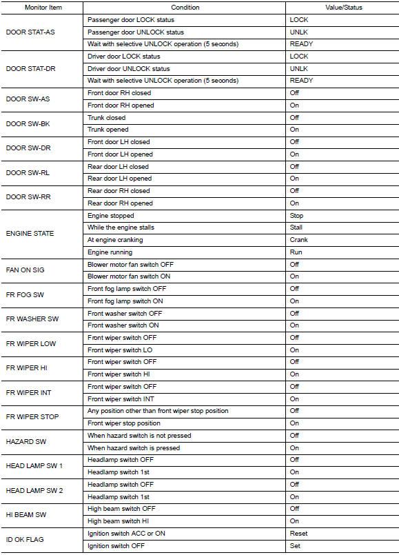
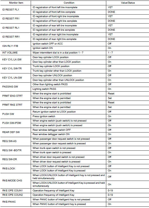
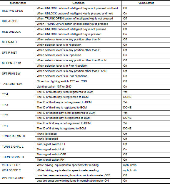
VALUES ON THE DIAGNOSIS TOOL
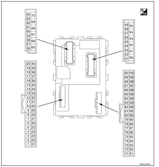
TERMINAL LAYOUT
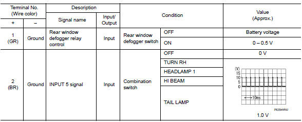
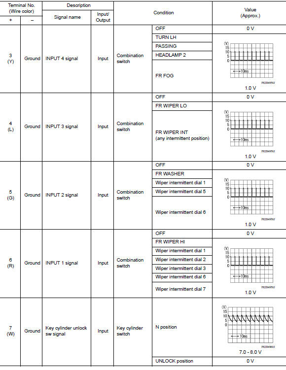
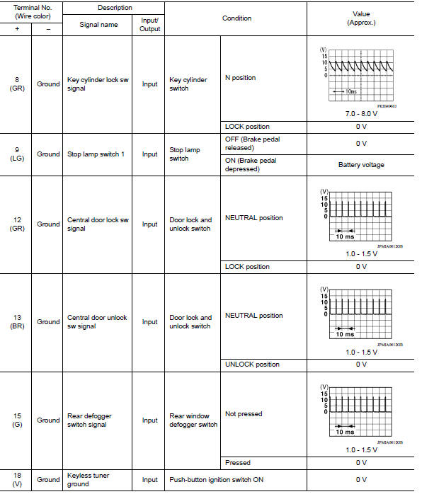
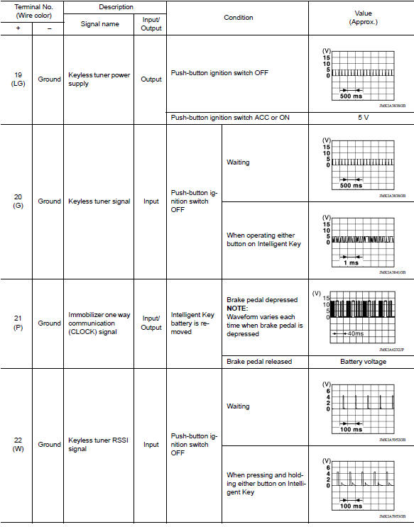
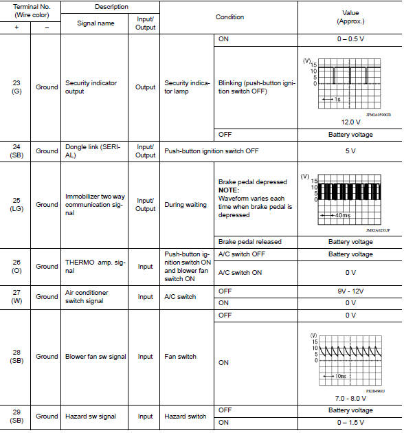
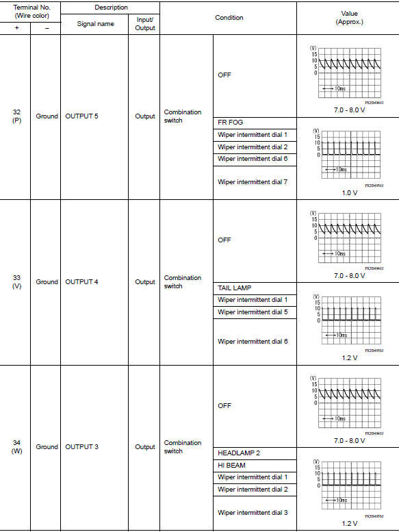
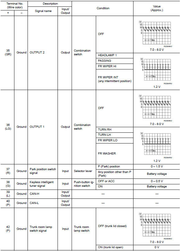
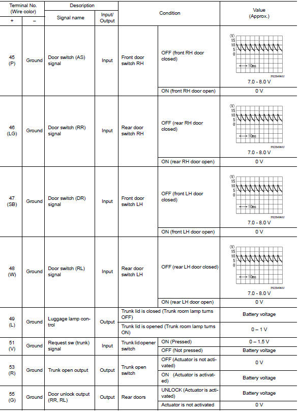
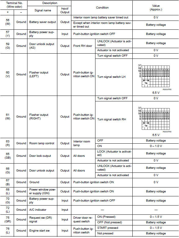
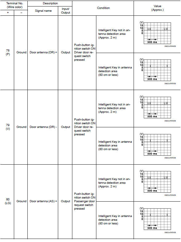
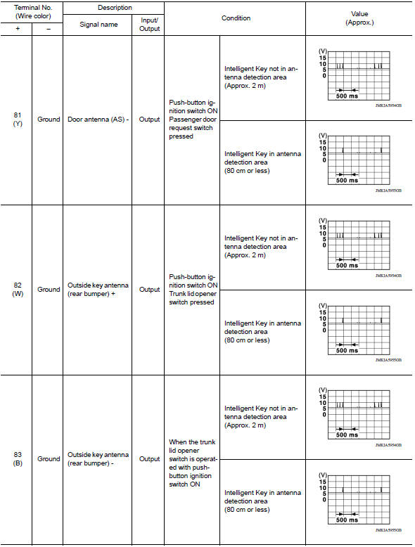
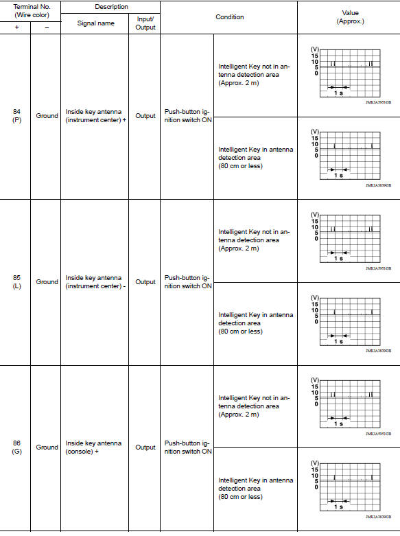
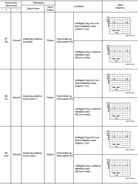
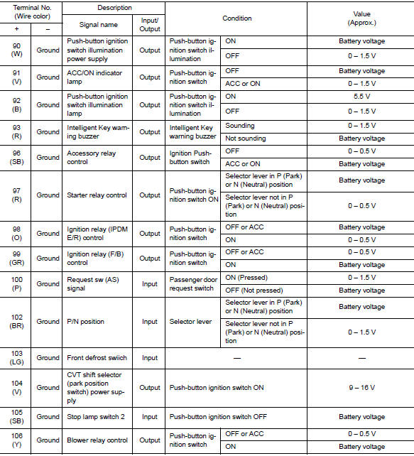
PHYSICAL VALUES
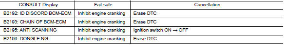
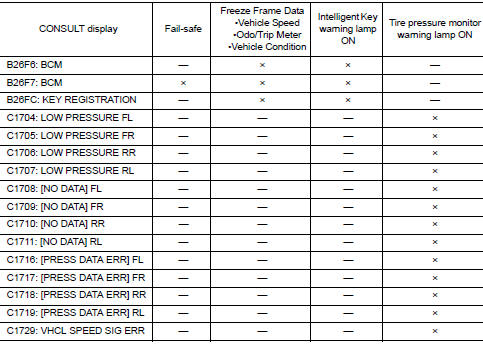
Fail-safe
BCM performs fail-safe control when the following DTCs are detected.
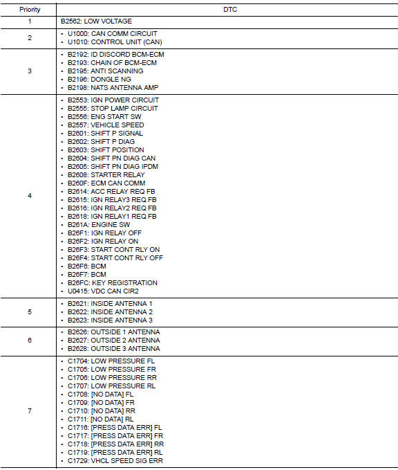
DTC Inspection Priority Chart
If more than one DTC is displayed at the same time, perform inspections based on the following priority chart.
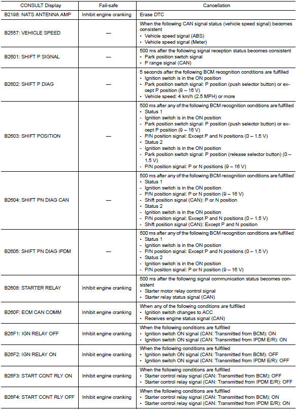
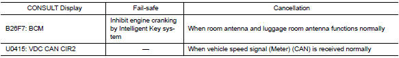
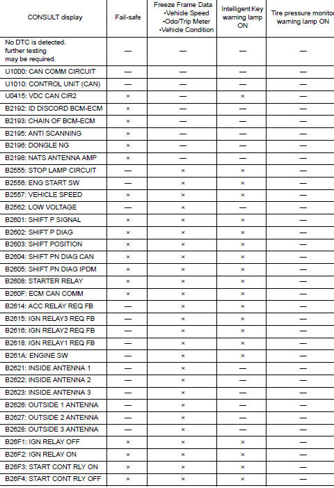
DTC Index
NOTE: The details of time display are as follows.
- CRNT: A malfunction is detected now.
- PAST: A malfunction was detected in the past.
IGN counter is displayed on Freeze Frame Data.
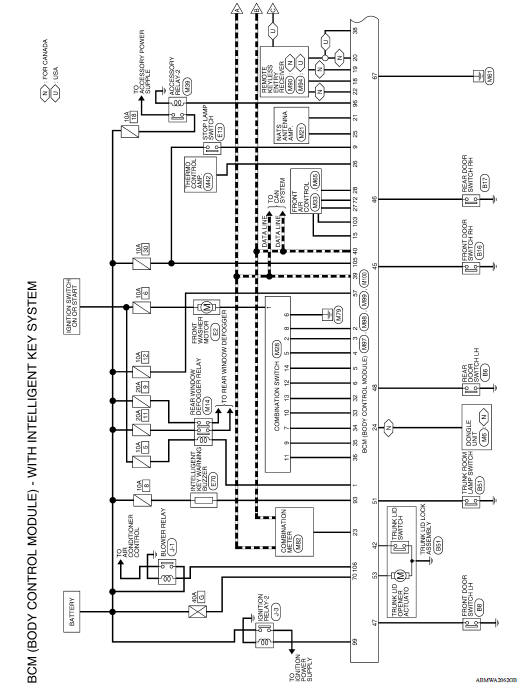
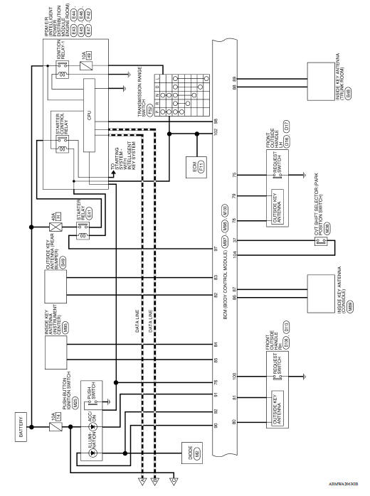
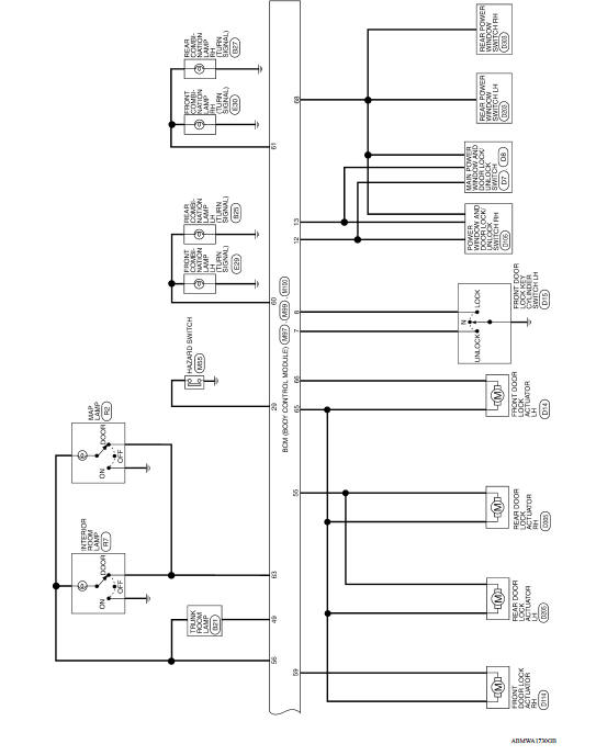
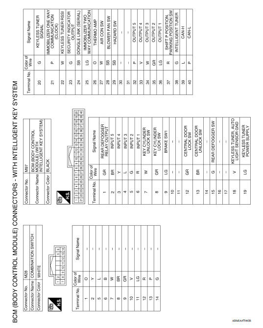
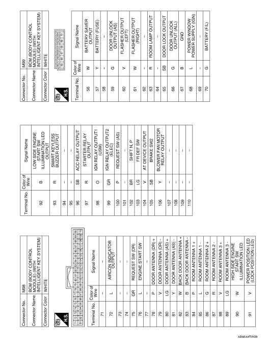
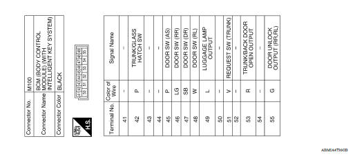
WIRING DIAGRAM
BCM
Wiring Diagram
BASIC INSPECTION
 Diagnosis system (BCM)
COMMON ITEM COMMON ITEM : CONSULT Function (BCM - COMMON ITEM) APPLICATION ITEM CONSULT performs the following functions via CAN communication with BCM. SYSTEM APPLICATION BCM can perform the ...

Other materials:
Exterior front
1. Engine hood
2. Windshield
3. Wiper and washer switch
4. Power windows (if so equipped)
5. Door locks. NISSAN Intelligent Key
(if so equipped). Key fob (if so equipped). Keys
6. Mirrors
7. Tire pressure. Flat tire. Tire chains
8. Headlight and turn signal switch. Replacing bulbs
9. Fo ...
Drive belt idler pulley
Exploded View
1. Generator bracket 2. Center shaft 3. Spacer
4. Adjusting bolt 5. Washer 6. Idler pulley
7. Plate
Removal and Installation
REMOVAL
Remove the fender protector (RH).
Remove the air duct inlet assembly.
Remove drive belt.
Remove the lock nut, and then remove the pl ...
Categories
- Manuals Home
- Nissan Versa Owners Manual
- Nissan Versa Service Manual
- Video Guides
- Questions & Answers
- External Resources
- Latest Updates
- Most Popular
- Sitemap
- Search the site
- Privacy Policy
- Contact Us

0.0047