Nissan Versa (N17): BCM (Body control module)
Removal and Installation
CAUTION: Before replacing BCM, perform "READ CONFIGURATION" to save or print current vehicle specification.
Refer to BCS "ADDITIONAL SERVICE WHEN REPLACING CONTROL UNIT (BCM) : Description".
REMOVAL
1. Disconnect the negative battery terminal. Refer to PG"Removal and Installation".
2. Remove instrument lower panel LH. Refer to IP "Removal and Installation".
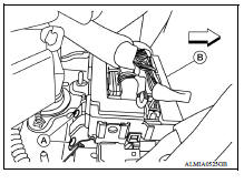
3. Remove BCM screws (A) and pull out the BCM (B).
4. Disconnect the harness connectors from the BCM (B) and remove.
INSTALLATION
Installation is in the reverse order of removal.
CAUTION:
- Be sure to perform "WRITE CONFIGURATION" when replacing BCM. Refer to BCS "CONFIGURATION (BCM) : Work Procedure".
- For Canada, be sure to perform the system initialization (NATS) when replacing BCM. Refer to BCS "CONFIGURATION (BCM) : Work Procedure".
- When replacing BCM, if new BCM does not come with keyfobs attached, all existing keyfobs must be re-registered.
 Combination switch output circuit
Diagnosis Procedure Regarding Wiring Diagram information, refer to BCS "Wiring Diagram". 1.CHECK OUTPUT 1 - 5 CIRCUIT FOR OPEN 1. Turn ignition switch OFF. 2. Disconnect BCM and combinat ...
Combination switch
Exploded View 1. Combination switch 2. Combination switch harness connector Front Removal and Installation REMOVAL 1. Remove the steering wheel. Refer to ST "Removal and Installation& ...
Other materials:
NISSAN Intelligent Key (if so equipped)
WARNING
Radio waves could adversely affect
electric medical equipment. Those who
use a pacemaker should contact the
electric medical equipment manufacturer
for the possible influences before
use.
The Intelligent Key transmits radio
waves when the buttons are pressed.
The FAA ad ...
Bluetooth Hands-Free Phone System without Navigation System (Type A) (if so
equipped)
WARNING
Use a phone after stopping your vehicle
in a safe location. If you have to use a
phone while driving, exercise extreme
caution at all times so full attention may
be given to vehicle operation.
If you are unable to devote full attention
to vehicle operation while talking on
...
Categories
- Manuals Home
- Nissan Versa Owners Manual
- Nissan Versa Service Manual
- Video Guides
- Questions & Answers
- External Resources
- Latest Updates
- Most Popular
- Sitemap
- Search the site
- Privacy Policy
- Contact Us

0.0051