Nissan Versa (N17): Combination switch output circuit
Diagnosis Procedure
Regarding Wiring Diagram information, refer to BCS "Wiring Diagram".
1.CHECK OUTPUT 1 - 5 CIRCUIT FOR OPEN
1. Turn ignition switch OFF.
2. Disconnect BCM and combination switch connectors.
3. Check continuity between BCM connector and combination switch connector.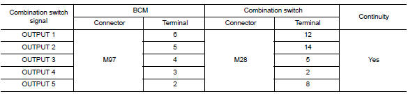
Is the inspection result normal?
YES >> GO TO 2.
NO >> Repair harness or connectors.
2.CHECK OUTPUT 1 - 5 CIRCUIT FOR SHORT
Check for continuity between BCM connector and ground.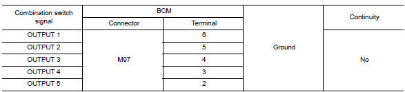
Is the inspection result normal?
YES >> Repair harness or connectors.
NO >> GO TO 3.
3.CHECK BCM INPUT SIGNAL
1. Connect BCM and combination switch connectors.
2. Turn ON any switch in the system that is malfunctioning.
3. Check voltage between BCM connector and ground.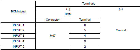
Is the inspection result normal?
Yes >> Replace BCM. Refer to BCS "Removal and Installation".
No >> Replace combination switch.
SYMPTOM DIAGNOSIS
COMBINATION SWITCH SYSTEM SYMPTOMS
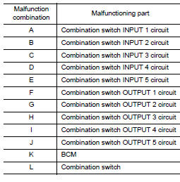
Symptom Table
1. Perform the data monitor of CONSULT to check for any malfunctioning item.
2. Check the malfunction combinations.
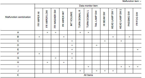
3. Identify the malfunctioning part from the agreed combination and repair or replace the part.
REMOVAL AND INSTALLATION
 Combination switch input circuit
Diagnosis Procedure Regarding Wiring Diagram information, refer to BCS "Wiring Diagram". 1.CHECK INPUT 1 - 5 CIRCUIT FOR OPEN 1. Turn ignition switch OFF. 2. Disconnect BCM and combinati ...
BCM (Body control module)
Removal and Installation CAUTION: Before replacing BCM, perform "READ CONFIGURATION" to save or print current vehicle specification. Refer to BCS "ADDITIONAL SERVICE WHEN REPLACING CONTROL ...
Other materials:
Electric ignition system
ELECTRIC IGNITION SYSTEM : System Diagram
ELECTRIC IGNITION SYSTEM : System Description
INPUT/OUTPUT SIGNAL CHART
Sensor
Input signal to ECM
ECM function
Actuator
Crankshaft position sensor (POS)
Engine speed*3
Piston position
Ignition timing control
Igni ...
Accelerator pedal released position
learning
Description
Accelerator Pedal Released Position Learning is a function of ECM to learn
the fully released position of the
accelerator pedal by monitoring the accelerator pedal position sensor output
signal. It must be performed each
time harness connector of accelerator pedal position senso ...
Categories
- Manuals Home
- Nissan Versa Owners Manual
- Nissan Versa Service Manual
- Video Guides
- Questions & Answers
- External Resources
- Latest Updates
- Most Popular
- Sitemap
- Search the site
- Privacy Policy
- Contact Us

0.0047