Nissan Versa (N17): Combination switch input circuit
Diagnosis Procedure
Regarding Wiring Diagram information, refer to BCS "Wiring Diagram".
1.CHECK INPUT 1 - 5 CIRCUIT FOR OPEN
1. Turn ignition switch OFF.
2. Disconnect BCM and combination switch connectors.
3. Check continuity between BCM connector and combination switch connector.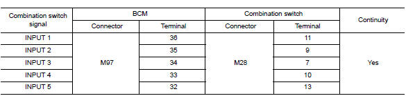
Is the inspection result normal?
YES >> GO TO 2.
NO >> Repair harness or connectors.
2.CHECK INPUT 1 - 5 CIRCUIT FOR SHORT
Check for continuity between BCM connector and ground.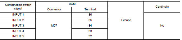
Is the inspection result normal?
YES >> Repair harness or connectors.
NO >> GO TO 3.
3.CHECK BCM OUTPUT VOLTAGE
1. Connect BCM connector.
2. Check voltage between BCM connector and ground.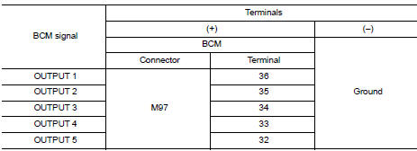
Is the inspection result normal?
YES >> Replace combination switch.
NO >> Replace BCM. Refer to BCS "Removal and Installation".
 Power supply and ground circuit
Diagnosis Procedure Regarding Wiring Diagram information, refer to BCS "Wiring Diagram". 1.CHECK FUSES AND FUSIBLE LINK Is the fuse blown? YES >> Replace the blown fuse or fusible ...
Combination switch output circuit
Diagnosis Procedure Regarding Wiring Diagram information, refer to BCS "Wiring Diagram". 1.CHECK OUTPUT 1 - 5 CIRCUIT FOR OPEN 1. Turn ignition switch OFF. 2. Disconnect BCM and combinat ...
Other materials:
Remote keyless entry system (if so equipped)
WARNING
Radio waves could adversely affect
electric medical equipment. Those who
use a pacemaker should contact the
electric medical equipment manufacturer
for the possible influences before
use.
The remote keyless entry key fob transmits
radio waves when the buttons are
pressed. ...
Camshaft
Exploded View
1. Camshaft bracket (No. 2 to 5) 2. Camshaft bracket (No. 1) 3. Camshaft
sprocket (EXH)
4. Exhaust valve timing control solenoid
valve 5. Oring 6. Camshaft sprocket (INT)
7. Plug (EXH) 8. Washer (EXH) 9. Oil filter (for exhaust valve timing control
solenoid valve)
10. Cylinde ...
Categories
- Manuals Home
- Nissan Versa Owners Manual
- Nissan Versa Service Manual
- Video Guides
- Questions & Answers
- External Resources
- Latest Updates
- Most Popular
- Sitemap
- Search the site
- Privacy Policy
- Contact Us

0.0049